closed switch to open signal
Printed From: the12volt.com
Forum Name: Relays
Forum Discription: Relay Diagrams, SPDT Relays, SPST Relays, DPDT Relays, Latching Relays, etc.
URL: https://www.the12volt.com/installbay/forum_posts.asp?tid=129000
Printed Date: April 19, 2026 at 11:47 AM
Topic: closed switch to open signal
Posted By: sn00ky
Subject: closed switch to open signal
Date Posted: October 29, 2011 at 9:28 AM
Hello Everyone.
Newbie here, found myself registering after I realized that I found links on this forum for several questions over the last while during my remote starter. Thanks to everyone on here for having such information.
So, I have installed a remote starter (Compustar CM6200) with Blade AL bypass, and Drone Mobile system in my truck. At this point, all is good.
What I am trying to do is figure out the wiring for a neutral safety switch. I understand, and have properly functioning the reservation mode, and fully understand the consequences of having remote start on my manual transmission truck.
I have at this point fabricated and installed a ball switch on my gear box shifter, which operates as discussed below. I have GWR available on my brain.
Below lists point form of my objectives.
Ball Switch - When truck is in neutral, switch closed, any other position, open. Reason for this, if switch fails, or has any issues, closer circuit should not be active, therefore, should disable my remote start. Sort of a fail-safe such that if not 100%, it's 0%.
GWR (Ground while running) - Available and operatable from CM6200 brain. Only shows ground feed while remote start is active - Open when truck is off, Open when key is "On". I would like to use this, such that I suspect a relay or 2 will come into play for this and would prefer the system to just do a "check" for neutral, instead of powering relay coil on and off while driving the truck, and also, do not want it powered while engine off (battery drain).
Hood Switch Pin - Operatable now. Requires to be Open to enable remote start. When it sees ground, constant or momentary, remote start is disabled, and reservation mode (due to manual transmission) is cancelled. This is the tricky part for me, because circuits I have started with have all yielded somehwere in the timing of it all, a ground connection to this wire.
So this is my biggest problem really, neutral swtich is "closed" when ready to start (neutral), yet my hood pin switch requires "open".
Hood Swtich Pin - Continued - I would like to use this particular wire simply because my Drone Mobile App can retrieve the status of my hood. Therefore, if my truck is in gear (my reservation mode will be cancelled and won't start), it will tell my "hood open", therefore, I can take this as a "truck in gear" status (though it could be my hood as well, but you know what I mean).
Have been thinking for days, just about full of gray hair now! Jk, but i certainly would apprecaite any input to this scenario. Slightly easier terminology is apprecaited as I am not exactly trained in this stuff, just stubborn and persistant enough to keep plugging away at it until it works. And its kinda fun!
Thanks everyone! Sorry for the length, but one thing I have learned is more info the better!
Weird, before I posted this, I was re-reading and thought of a possible way. I have it drawn out, forgive the diagram, not exactly "professional".
I am believing this might work, but would like confirmation....what do everyone think? Thanks!!!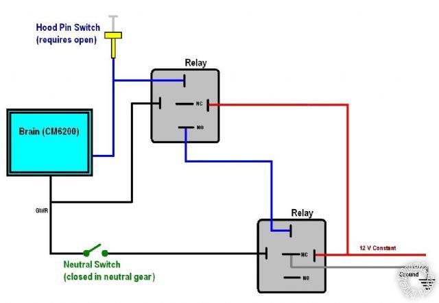
------------- Snooky
Replies:
Posted By: howie ll
Date Posted: October 29, 2011 at 10:11 AM
Surely simply running pin 2 CN3 light blue to ground via your switch will do all you want?
Since you broke the rules by not mentioning your vehicle, I suggest you access the engine management pin-outs, there's often a NSS already in existence, e.g. Nissan, Subaru etc.
-------------
Amateurs assume, don't test and have problems; pros test first. I am not a free install service.
Read the installation manual, do a search here or online for your vehicle wiring before posting.
Posted By: sn00ky
Date Posted: October 29, 2011 at 10:34 AM
Completely apologize about not mentioning the truck, got totally overwelmed with the contents of the post and forgot the basics!
2008 F350 Superduty, 6.4L Diesel, Manual Transmission
Regarding the NSS, my understanding is that there is none on the truck already, except of course for a reverse gear for the lights. I havn't found any information related to that. Hence the reason I am going through all of this trouble.
Again, sorry about the vehicle information. ------------- Snooky
Posted By: howie ll
Date Posted: October 29, 2011 at 10:43 AM
The reason I mentioned this is the hood switch has to see an open circuit and the neutral safety a ground (0v). Thus going through your switch to ground WILL do the trick.
The point being that although I might well be wrong, many vehicles have inbuilt NSS systems and it's worth checking, either on-line or your local library. Normally on the engine ECU.
I thought so about vehicle exclusion, the rest of your post was too thorough.
A reverse light switch is NOT the same as a neutral safety switch.
-------------
Amateurs assume, don't test and have problems; pros test first. I am not a free install service.
Read the installation manual, do a search here or online for your vehicle wiring before posting.
Posted By: howie ll
Date Posted: October 29, 2011 at 10:46 AM
But it may be physically combined with the reversing light gearbox switch. That is, a 4 wire switch instead of two.
-------------
Amateurs assume, don't test and have problems; pros test first. I am not a free install service.
Read the installation manual, do a search here or online for your vehicle wiring before posting.
Posted By: sn00ky
Date Posted: October 29, 2011 at 10:51 AM
I think I understand your first bit there, however the problem with that is my switch is a closed circuit when in neutral. Putting this to ground would be a 180 of what I need? Maybe I dont understand.
I hear ya about reverse light / switch. What I really meant was, I could easily use the reverse light as a signal, however that would only cover my reverse gear, and not the rest.
Lets just say for kicks and giggles, that there is no NSS on my vehicle, may I have your opinion on the diagram above?
If that does suffice, I just want to be sure that it will be safe and not drain my battery. Which I believe it should be good?
Thanks! ------------- Snooky
Posted By: howie ll
Date Posted: October 29, 2011 at 12:10 PM
A closed circuit = ON. That is joined together, NC etc. Your diagram is unecessary.
-------------
Amateurs assume, don't test and have problems; pros test first. I am not a free install service.
Read the installation manual, do a search here or online for your vehicle wiring before posting.
Posted By: sn00ky
Date Posted: October 29, 2011 at 12:43 PM
I don't understand your post. I know that a closed circuit has "continunity" per say. But that is the problem.
If I don't use that diagram, then when in neutral, my switch is closed. Therefore, if it is going to ground, my hood wire will have ground when in neutral, which means my truck will not start - reservation mode cancelled.
Unless, you are referring to your suggestion about the light blue wire above. Which I believe to be the brake wire. Does that light blue wire see ground when brake pedal is pressed? 12v? or open? I need to look into that particular scenario more to understand. ------------- Snooky
Posted By: howie ll
Date Posted: October 29, 2011 at 1:21 PM
Forget the hood wire!!!
Use the wire I mentioned, if it doesn't see ground then the RS simply won't work.
-------------
Amateurs assume, don't test and have problems; pros test first. I am not a free install service.
Read the installation manual, do a search here or online for your vehicle wiring before posting.
Posted By: howie ll
Date Posted: October 29, 2011 at 1:42 PM
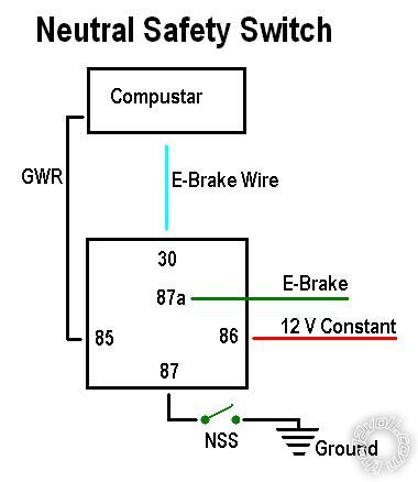
Please forget my last post! I was wrong, this is what you need to do:-
DD5_nss.bmp
At rest the NSS (or ebrake) wire sees 12V+, thus disabling the RS. The black GWR wire changes the relay so that 30 is now connected to 87.
Of course that wire at 30 won't see a ground, STILL disabling the RS until the gear shift is in neutral.
As a double redundant safety, I just revised the diagram allowing blocking diodes. :- F6E_nss.bmp
Sorry about that, it's dinner time here and I'm thinking this through and designing the circuit as I write! ------------- Amateurs assume, don't test and have problems; pros test first. I am not a free install service.
Read the installation manual, do a search here or online for your vehicle wiring before posting.
Posted By: sn00ky
Date Posted: October 29, 2011 at 3:02 PM
Thanks!
I totally was second guessing and reviewing diagrams like crazy!
Totally appreciate the diagrams....do you feel diodes are necessary? Luckily I have some still as I bought extra when I wired my door triggers (isolated open circuit).
When you say "At Rest", do you mean when e-brake is NOT engaged? Meaning, no light on my dash? If so this make sense because e-brake on would be like sending the light blue / white wire (or light blue, whichever), to ground.
Meaning, e-brake requires ground, which I will interrupt with this relay / switch combo you made up for me....
Right track?? ------------- Snooky
Posted By: sn00ky
Date Posted: October 29, 2011 at 3:20 PM
Actually, looking a little closer, it looks like it requires either of the 2 to satisfy. Either e-brake engaged, OR the NSS closed (in neutral) to supply a ground?
If that is the case, could I do this?
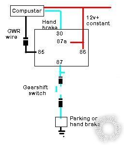
------------- Snooky
Posted By: howie ll
Date Posted: October 29, 2011 at 4:17 PM
Yes I do mean not engaged when at rest.
No follow my second diagram, when wired in parallel rather than series, both have to be on. In series as you drew it the handbrake is not going to do anything, it still has to pass through the gear switch, thus stick with my version.
-------------
Amateurs assume, don't test and have problems; pros test first. I am not a free install service.
Read the installation manual, do a search here or online for your vehicle wiring before posting.
Posted By: sn00ky
Date Posted: October 29, 2011 at 5:49 PM
Well I have been looking this over ever since, and I just don't understand.
I am very sorry for being so difficult, however, I can't see how that works.
My reasoning is that the 12v constant is looped through 87a - therefore, when GWR is not active (any time engine is off and RS not active), there will be a 12v signal going to my brain. My understanding is that this will cancel my reservation mode.
Secondly, and more frustrating to you and me I am sure, is that I do not get how the parallel would work. My understanding is that GWR active, so coil is energized, making contact between 30 and 87. Brain is looking for ground signal on light blue wire. If e-brake is engaged, this will send blue wire to ground. Also, if gearshift is in neutral (NSS Closed), it will send blue wire to ground. It seems to me that as long as 1 sees ground, and the opposite could be "open", due to not engaged on switch or e-brake, that it will be just a dud wire, and the ground connection will still pass through to the brain?
Boy, this stuff can be frustrating to someone of my experience level. Yet, it is still fun!
------------- Snooky
Posted By: howie ll
Date Posted: October 29, 2011 at 5:57 PM
Just try it as a patch and see if it works, remember I've done all this on the fly, I've never seen a query like this before, congratulations by the way by my counting you're only the second person with an original post this year! 99.9% are re-treads, fools not checking the archives, any way, just try it. The parking brake is secondary, it won't stop you if you are downhill and in gear.
-------------
Amateurs assume, don't test and have problems; pros test first. I am not a free install service.
Read the installation manual, do a search here or online for your vehicle wiring before posting.
Posted By: sn00ky
Date Posted: October 29, 2011 at 6:31 PM
Cool! Sounds like an achievement!
I will totally be trying it, without a doubt, just at work right now. I will buck it up this evening likely. Just trying to educate myself as best I can.
I have still got a bunch of stuff to hook up yet, including a door by-pass, and a momentary switch for my clutch by-pass.
Coolest part of my install yet thou, is that I can elevate my idle to a preset value via my DroneMobile app, or remote of course (I have my SEIC high-idle mod using a potentiometer for variable RPMS rigged up to my auxilliary outputs on the starter). Man are the guys jealous of that one!!!
One other thing - Though I have every intention of trying your suggestion - I still am leaning towards using the hood switch at the end of the day. Reason being is that Compustar 2way allows me to know that my hood is open via remote or my phone app - Using this lead to kill the RS would be kick - butt cool in my opinion because them I have ability to know if my truck is in gear.
That being said....can you think of any reason why my original wiring would not work or be not recommended? Curiousity more than anything. I like to understand:)
Thanks again!
------------- Snooky
Posted By: howie ll
Date Posted: October 30, 2011 at 12:42 AM
Easy answer why not.
RS has to see an OPEN circuit i.e. nothing.
Going to ground (0v)will disable RS.
The light blue wire HAS to see ground (0v) to enable RS.
If that light blue sees an open circuit, it won't affect it.
BUT if it sees 12v+, it WILL disable the RS.*
That is what you are trying to achieve to give you a safe RS on a manual.
*Same principle as hand brake (A.K.A. parking, ebrake), that wire shows a pos on ignition if brake is released from the bulb. Engaging the parking brake pulls up the switch and completes the circuit by grounding at the switch, thus going to ground (0v) and switching on the warning light.
Thus the hood pin and the light blue are completely different functions, don't join, apart from which your original plan uses an extra relay, and is a kludge circuit wise.
-------------
Amateurs assume, don't test and have problems; pros test first. I am not a free install service.
Read the installation manual, do a search here or online for your vehicle wiring before posting.
Posted By: sn00ky
Date Posted: November 02, 2011 at 9:36 PM
Well, still havn't had a change to wire up that circuit. Have got tied up with other things this last week. Hopefully next few days will yeild some time to play!
------------- Snooky
Posted By: sn00ky
Date Posted: November 04, 2011 at 12:45 AM
Ok, so I wired up the second version of circuit . No luck.
I checked the status of the GWR wire, and it remained open. Also, I was unable to set my truck to ready mode. So this is what I think. Because the 12V is being supplied on 87a constant - RS sees e-brake as "not engaged". Since this is the case, it is not attempting to go to ready mode (I know this because it isn't "clicking" inside like it usually does indicating that I am able to turn off my key w/out the engine shutting off immediately). The GWR wire is only actually ground when the RS is active (after the click), so the circuit from 30 to 87 is not closing, allowing the e-brake / NSS to be involved.
So, with that being said, the only difference is that I did not use the diodes as indicated - I didn't have them handy at the time. However, I do not think it matters considering that side of the circuit isn't able to engage.
Any ideas?? ------------- Snooky
Posted By: sn00ky
Date Posted: November 04, 2011 at 1:07 AM
I have attempted another circuit on the e-brake. I have tried this as well, with no luck. It keeps cycling through the stages of ready mode - cancelling GWR wire, resetting relays, click click click....argggg.
Here it is below. Might be of no use, however, another angle to look at!
------------- Snooky
Posted By: sn00ky
Date Posted: November 05, 2011 at 9:51 PM
Well, looked at everything again, still no luck. Havn't found a work around for howie II 's circuit either. I spent some time at the truck with an DVM and tested each line and followed the order of "clicking" relays....and it all confirms my ideas above. Almost kinda sings a song to me! LOL!
Anyways, I am now at the point of looking back at my original idea once again. I have just picked up the relays and harnesses required and will be trying to wire it up tonight. See how it works.
I heard from a friend that there are such programs available, he had one before, that allows you to build a virtual circuit, including relays, diodes, etc and allows you to "run it". Which I can only assume, allows you to apply voltage here, flip this switch, engage that, etc. Sounds cool. is anyone familiar with this type of software? Would it be a freeware? Probably not, but sounds pretty cool!
Thanks again! ------------- Snooky
Posted By: howie ll
Date Posted: November 06, 2011 at 1:10 AM
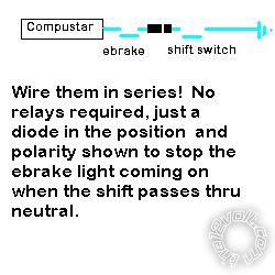
I had a rethink:-
E1F_nss.bmp------------- Amateurs assume, don't test and have problems; pros test first. I am not a free install service.
Read the installation manual, do a search here or online for your vehicle wiring before posting.
Posted By: sn00ky
Date Posted: November 06, 2011 at 1:36 AM
I thought of that, but did not think of the diode! Good job....!
Will this stop my e-brake from coming on when it is in gear?
Thanks again for your help ------------- Snooky
Posted By: howie ll
Date Posted: November 06, 2011 at 2:23 AM
Yes now go to sleep, because I've just had my breakfast! Nearly 8:30am!
-------------
Amateurs assume, don't test and have problems; pros test first. I am not a free install service.
Read the installation manual, do a search here or online for your vehicle wiring before posting.
Posted By: sn00ky
Date Posted: November 06, 2011 at 4:13 AM
Hahha, no kidding!
I am actually at work right now (working night shifts) lol! I am crazy, not that crazy! ------------- Snooky
Posted By: howie ll
Date Posted: November 06, 2011 at 4:55 AM
Not as bad as me emailing from my phone whilst stuck in traffic.
-------------
Amateurs assume, don't test and have problems; pros test first. I am not a free install service.
Read the installation manual, do a search here or online for your vehicle wiring before posting.
|