Hi everyone,
I'm trying to design a circuit with the following diagram:
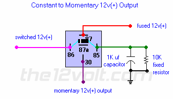
I am designing a custom dash for my 86 pickup, with custom warning lights, and I'm trying to build a circuit that will present power to all of the LEDs in the dash for about 3 seconds when I turn my ignition on (as a test feature to make sure all lights are working). I was thinking of using a circuit like this, and then diode-isolating the 30 output of the relay to each LED. I built a mock-up of this circuit on a breadboard, and everything is working, except for the timing.
Currently, with a 1K uF capacitor, it holds the circuit on for about 1/2 second. So I added 3 1K uF capacitors in parallel, and no change. I was hoping the increased capacitors would increase the charge time of the capacitors, but it doesn't look like that is the case. So I was thinking if I want to multiply the time by 6, could I get a 6K uF capacitor? But having a hard time finding one.
Any suggestions on what I can do?
Also, in the diagram above, I used the switched 12v for hot as well (in other words the pink and red wires above both go to switched (ignition) 12v.
When I energize the circuit and it holds the relay on for 1/2 second then closes, and I remove power from the circuit, I have to wait several minutes before I can do it again. If I apply power to the circuit again, nothing happens. I think it is waiting on the capacitors to discharge. Any thoughts?
Thanks.
Or you could play the kiss card and use either a 528t or 611t timers from DEI.
-------------
Amateurs assume, don't test and have problems; pros test first. I am not a free install service.
Read the installation manual, do a search here or online for your vehicle wiring before posting.
For anyone interested, I did figure it out. Kept the three 1K uF caps, and added two 4700 uF caps in parallel. It does the trick. Holds the circuit on for about 4 to 5 seconds, exactly what I was looking for.
My only problem is I have to wait for the caps to discharge first before the circuit works again. To test, I've just been shorting the caps out with a screwdriver, it works fine. Kinda hard to do that when it's running tho. I was thinking of hooking a wire to a different relay to short it out when it loses accessory power, but Im worried that it may cause a draw on the battery when the whole vehicle is off...
The diode from 85 to 86 should discharge the cap assuming a typical IGN circuit (ie, enough load(s) to ground the switched IGN +12V side).
Did you fit the diode? Or has it blown due to high cap current?
Most vehicles of that vintage use the charge light circuit as a lamp test, but that's where all lights/LEDs use GND switching (each LED/lamp to be tested has its GND thru a diode to the D+ or L (chargeLamp) alternator output). They extinguish when the alternator starts charging (or rather, they light whenever the IGN is on and the alternator is not charging).