single pulse on/off latch relays
Printed From: the12volt.com
Forum Name: Relays
Forum Discription: Relay Diagrams, SPDT Relays, SPST Relays, DPDT Relays, Latching Relays, etc.
URL: https://www.the12volt.com/installbay/forum_posts.asp?tid=130725
Printed Date: May 07, 2026 at 6:52 PM
Topic: single pulse on/off latch relays
Posted By: trbolexis
Subject: single pulse on/off latch relays
Date Posted: February 24, 2012 at 1:43 AM
I would like to know if anyone has a design for a single pulse or dual pulse on/off latching system, that can be used to output different set resistance values. for each latch; 5 in total.
I'm not sure how easy that was to follow, so i will elaborate on the use.
I have an EFI system that can use a Potentiometer to adjust a preset variable in the software. It can adjust for 5 separate preset resistances on the same wire (1 to 5 volts input). I also have a steering wheel with 2 momentary switches currently unused. i would like to be able to press a switch once, to output 'x' voltage to the input on the EFI unit. Press it again to output 'y' voltage. Press it again to output 'z' .. etc. It would be fine for the process to repeat after the 5th preset.
is there any replay latching stystem, or microprossessor that can do this?
Replies:
Posted By: trbolexis
Date Posted: February 24, 2012 at 1:56 AM
Basically, i would like to make the momentary switch toggle 5 defferent predefined loads, starting at 1V to 5V. Supply voltage is 5V.
Posted By: itsyuk
Date Posted: February 24, 2012 at 11:33 PM
sounds like a good job for a DEI 450T and an array of small relays.
it would work perfect. ------------- yuk
quiet rural missouri, near KC.
If your system moves you physically and not emotionally, you have wasted your money.
Posted By: hotwaterwizard
Date Posted: March 21, 2012 at 9:31 PM
 ------------- John DeRosa (Hotwaterwizard)
Stockton California
When in doubt, try it out !
Posted By: oldspark
Date Posted: March 21, 2012 at 11:09 PM
Sounds like a good application for a CD4017 decade counter - a $3 16-pin chip.
To make it a "divide by n" counter, connect output n to the reset pin (#15).
EG for divide by 5, connect output #5 (pin #1) to pin #15.
That assumes that on power-up, output #0 (pin #3) drives the first relay, output #1 the 2nd, #2 the 3rd, #3 the 4th, & #4 the 5th relay.
The next switch push (aka clock) moves the output to #5 which rests it back to output #0 = relay #1.
You may not need the first relay.
I'd try to do it so the highest value resistance is soldered across the EMS input, then use the other relays to switch in different parallel resistors so that the combined parallel resistance equals the resistance you need (which is lower than the hardwiRED / soldered "default" resistor).
That minimises the chances of an open-circuit that might be detrimental.
Posted By: trbolexis
Date Posted: May 21, 2012 at 10:26 PM
AMAZING! Thank you for all the help and suggestions!
Posted By: trbolexis
Date Posted: May 21, 2012 at 10:49 PM
Could I use the outputs to directly drive particular restiances to the input device?
Posted By: oldspark
Date Posted: May 22, 2012 at 2:24 AM
Der.... yes.
Posted By: KPierson
Date Posted: May 22, 2012 at 7:08 PM
Have you checked the switches in the car yet? They typically are multiplexed to begin with which may add a layer of complexity to decoding the switch signal and then processing it.
-------------
Kevin Pierson
Posted By: trbolexis
Date Posted: May 22, 2012 at 8:52 PM
No. I have to an input to a digital input line on the ECU. It needs to vary from 0V to 5V because the ECU converts the input to ADC. I need the 5V broken down into 1V, 2V, 3V, 4V, 5V - each step will represent a breakpoint in the software to change a parameter.
I was considering using diodes to create the voltage drop, straight out of the CD4017B without need for any relays or otherwise. I was thinking 1B914 switching diodes because they actually have a forward voltage drop of 1V.
So Q1 of the chip would be 5V, Q2 would be 4V (after going through the diode, Q3 would be 3V (after going through 2 diodes), in theory of coarse.
Does this sound plausible?
Posted By: KPierson
Date Posted: May 22, 2012 at 9:34 PM
I would not rely on voltage drops of diodes. Use a voltage divider circuit for each output instead. With precision resistors you'll get much more predictable results.
-------------
Kevin Pierson
Posted By: trbolexis
Date Posted: May 23, 2012 at 1:41 AM
Would something like this on the Outputs of the CD4017B work?

Posted By: oldspark
Date Posted: May 23, 2012 at 4:26 AM
The 1N914 voltage drop varies with current and temperature.
But the above circuit with the diodes feeding linear trimpots should be ok.
The trimpots should be 50k, though 20k is probably ok (10k is too low).
The voltage for the 4017 will have to be ~6V or higher (if you want a 5V output - ie, diode drop at 0.1mA is ~0.5V & the 4017 output drops ~0.4V). An 8V supply should be ok.
The trimpots are connected as per your diagram - ie, between the 4017 output and 0V with the wiper to the ECU (via the 1N914 etc).
That circuit depends somewhat on the ECU input impedance, and assumes the input references to 0V/GND (ie, pulls "down").
In retrospect, I'd use a PICAXE - eg, the 08M2 - where input pulses can increment its DAC output to 5V.
That's merely an 8-pin PIC-08M2 with 78L05 regulator (etc) and its 2 "serial" programming resistors. But then you need the serial interface for programming, and the program....
But the you simply program the increments, and there is no variation with temperature or trimpot stability
Posted By: trbolexis
Date Posted: May 23, 2012 at 10:38 AM
The ECU input is a 51k pull down if that changes any of the info provided. Thanks for all the help so far!
Are the diodes absolutely required in the above diagram? I figured they would be as each output is tied to a ground through a pulldown resistor.
Posted By: trbolexis
Date Posted: May 23, 2012 at 11:56 AM
Something like this? What would heat dissipation be like if I trim the 12V down to 1V using the trimpot? There isnt much current flow, so I'd imagine very minimal?
I am still new to all this, so I'm trying to grasp an understanding.
Thanks for all your time.
Posted By: trbolexis
Date Posted: May 23, 2012 at 11:56 AM
Posted By: oldspark
Date Posted: May 23, 2012 at 4:54 PM
The 20k to 50k was based on the 4017 outputs sourcing ~2mA minimum with a 5V supply. 20k was borderline at low voltage for a "low spec" device.
Assume 15V/20k = 15x15/20k = 12mW max. (ie, an extreme of 15V thru the smaller 20k pot for max current/power)
51k pulldown is good - ie, an ECU open circuit will be "GND", and the 51k is reasonably negligible to the trimpot, though some readjustment will be necessary "in circuit".
The diagram is correct but check the pin numbers.
The "first" output (0) is pin 3 which should be not connected if "default" is to be 0V. (IE - the 0V output is any time a 4017 output does not supply voltage...)
Pin numbering in "output order" is 3, 2, 4,7, 10, 1, 5, 6, 9, 11.
Remember to connect reset (15) to the output pulse you want to reset (ie, the output after your last "latched" output.
And pin 13 (Clock Enable) to GND.
Reset (15) might need to be an RC to ensure POR "Power-On Reset" ie - starts at 0 output (pin 3).
Posted By: trbolexis
Date Posted: May 24, 2012 at 1:29 AM
The only outputs should be, 1V 2V 3V 4V and 5V. Zero will never be a desired output.
Pin 1 on the 4017 will need to be tied to RST(15).
Ill put all this together on the breadboard tomorrow.
What would be an suitable rebouncing circuit? The high input to the device will be 5V. A 555 timer? Cap?
I've learned a great deal so far. Thank you!
Posted By: trbolexis
Date Posted: May 24, 2012 at 1:44 AM
Debouncing*
Posted By: oldspark
Date Posted: May 24, 2012 at 3:14 AM
Switch debouncing is a pain...
The safest is to use a Schmitt inverter like the 74HC14 even if you only need the one inverter...
But NOT a 74HC14 because it is limited to a max 6V supply - hence use equivalents like the CD40106 or MC145848. (Probably any "Schmitt gate" that can be powered by your 4017's supply voltage; "gate" means AND, NAND, etc.)
A simple RC might work depending on how long the push is etc.
I dislike 555s for their high current consumption (10mA) and other issues. (I love them as a chip, but not for applications which are not strictly timer or frequency applications.)
Have a look at these sites for ideas: all-electric debounce, ikalogic de-bouncing-circuits, & eetimes Solving-Switch-Bounce-Problems.
The trick is if your switch output is +5V, something that can debounce that yet be high enough for the 4017 "high" clock...
Since the 4017 must be powered from higher than +5V in order to output +5V to the EMS/EFI...
You might begin to see why an 8-pin programmable chip is easier for this sort of circuit. The debounce is thru software, the output voltage is from the "clock" incrementing its DAC output in 1V increments...
Posted By: trbolexis
Date Posted: May 24, 2012 at 12:07 PM
Looks like a programmable chip would be better .. Let me look into this.
Posted By: trbolexis
Date Posted: May 24, 2012 at 4:27 PM
Okay,
The microcontroller is the way to go. However I need a GREAT deal of assistance with programming the chip.
On powerup, the chip should output 203 ADC at 'X' Pin. Then on a Pulse in, on 'Y' Pin, it should output 406 ADC at the initial pin (X). On next pulse in on 'Y', output should be 609 ADC on pin X.
So, with button press, desired outputs would be as follows
Press1, 204ADC (1 Volt)
Press2, 408ADC (2 V)
Press3, 612ADC (3 V)
Press4, 816ADC (4 V)
Press5, 1020ADC (5 V)
Now, my next question. Is there anyway to write the last state (ADC output) to back to the chip in order to retain its output the next time its powered up?
This is all excellent info so far! Thank you!
Posted By: trbolexis
Date Posted: May 24, 2012 at 4:54 PM
Upon further reading, I've learned that the 08M2 must use PWM on an output pin to create a pseudo analog voltage output with a Cap And resistor.
Can someone help me on designing such a circuit? i.e. what size cap and resistor? Also, is this going to be a trial and error sorta deal to figure out the appropriate PWM frequency?
Posted By: oldspark
Date Posted: May 24, 2012 at 7:01 PM
No, you use the DAC output - Digital to Analog, not the ADC (Analog to Digital).
The 08M2 is the first 08 with a DAC. Not that I have confirmed its existence - apparently the documentation is confusing. (IE - the prelim docs specify a DAC but product specs don't - though it was a few months ago that I looked...)
If using PWM, the RC constant needs to be much greater than the PWM frequency. Something like 1mS to 1Sec should be enough (unless 1 sec is too slow for your EFI reaction...)
Posted By: trbolexis
Date Posted: May 24, 2012 at 7:10 PM
Ahhh ... I read your post after perfecting my code. LOL
[code]symbol varA = b0
symbol varB = b1
symbol varC = b2
symbol varD = b3
symbol varE = b4
symbol varF = b5
symbol varG = b6
symbol varH = b7
symbol varI = b14
symbol varJ = b15
symbol varK = b16
symbol varL = b17
symbol varM = b18
symbol varN = b19
symbol varO = b20
symbol varP = b21
symbol varQ = b22
symbol varR = b23
symbol varS = b24
symbol varT = b25
symbol timer = time
let dirsC = %00000001
main:
label_106:
prc_STAGESELECT:
read 0,varA
if varA = 0 then label_143 'Compare command
if varA = 1 then label_145 'Compare command
if varA = 2 then label_151 'Compare command
if varA = 3 then label_152 'Compare command
if varA = 4 then label_153 'Compare command
goto label_106
label_153: goto prc_IBOOST5 'Goto
loop0:
goto loop0
prc_IBOOST5:
label_133: pwmout 2 , 99 , 400
if pinC.1 = 1 then label_135 'Decision command
goto label_133
label_135:
if pinC.1 = 0 then label_136 'Decision command
goto label_135
label_136: pause 500 'Wait command
let varA = 0 'Expression command
write 0,varA
goto prc_STAGESELECT 'Goto
loop1:
goto loop1
label_152: goto prc_IBOOST4 'Goto
loop2:
goto loop2
prc_IBOOST4:
label_125: pwmout 2 , 99 , 320
if pinC.1 = 1 then label_127 'Decision command
goto label_125
label_127:
if pinC.1 = 0 then label_128 'Decision command
goto label_127
label_128: pause 500 'Wait command
let varA = varA + 1 'Inc command
write 0,varA
goto prc_STAGESELECT 'Goto
loop3:
goto loop3
label_151: goto prc_IBOOST3 'Goto
loop4:
goto loop4
prc_IBOOST3:
label_117: pwmout 2 , 99 , 240
if pinC.1 = 1 then label_119 'Decision command
goto label_117
label_119:
if pinC.1 = 0 then label_120 'Decision command
goto label_119
label_120: pause 500 'Wait command
let varA = varA + 1 'Inc command
write 0,varA
goto prc_STAGESELECT 'Goto
loop5:
goto loop5
label_145: goto prc_IBOOST2 'Goto
loop6:
goto loop6
prc_IBOOST2:
label_95: pwmout 2 , 99 , 160
if pinC.1 = 1 then label_101 'Decision command
goto label_95
label_101:
if pinC.1 = 0 then label_115 'Decision command
goto label_101
label_115: pause 500 'Wait command
let varA = varA + 1 'Inc command
write 0,varA
goto prc_STAGESELECT 'Goto
loop7:
goto loop7
label_143: goto prc_IBOOST1 'Goto
loop8:
goto loop8
prc_IBOOST1:
label_80: pwmout 2 , 99 , 80
if pinC.1 = 1 then label_82 'Decision command
goto label_80
label_82:
if pinC.1 = 0 then label_114 'Decision command
goto label_82
label_114: pause 500 'Wait command
let varA = varA + 1 'Inc command
write 0,varA
goto prc_STAGESELECT 'Goto
loop9:
goto loop9
[/code]
Posted By: oldspark
Date Posted: May 24, 2012 at 7:47 PM
Not that I'm into the coding yet... And not that I understand your varB-T declarations etc.
But yes, setting one pin/leg as output.
Then I'd output the 1V, clear the "keypress" counter, and loop awaiting interrupt or loop-poll the switch input. (switch = key etc - whatever names suit you)
Implement the switch debounce code (as per some of my previous web links) and increment the keypress counter -cum- output voltage.
Check that switch=0 (after debounce) before the next increment.
Decide if you want the output change to occur on switch/key press or release (ie, many PC triggers are on button release).
Loop for switch polling or next interrupt.
(The older 08s did not have interrupts.)
Later add a pin to drop of output voltage etc (eg, and engine-blown alarm or temp sensors etc to kill the boost). That's the beauty of it - it's just additional programming...
And the 08M2 could be in the EMS and use its +5V hence minimising noise and components. (They only use mA...)
Only 2 or 1 wires out - ie, to the switch, & for serial programing - though those 2 could be combined. Plus optional gnd for the switch and serial...
I'd use the DAC output, but PWM with RC is "the same".
Oh - and I'd use meaningful labels - eg, debounceLoop, keyWait, incKyCount, incVout etc.
But that is all to taste and varies not only with experience, but even as the program evolves. (EG - deciding to move from item-function-instance to function-item etc (incKey, incOut or keyInc, outInc, or Key+, Out+ etc etc.)
LOL - when I look back at my early "program comments" that were mere English descriptions of the commands or mnemonics with label-1 & loop-3 etc...
Later programs were a description for each "section" (if needed) followed by the code which had rare comments. Usually the variable and goto and loop names/labels were self explanatory.
Posted By: KPierson
Date Posted: May 24, 2012 at 9:48 PM
As far as remembering the last state you should be able to store the current value in an EEProm register and call that register at each start up. If you plan to push the button a lot then you should look in to a circular EEProm programming configuration as most EEProm have a fairly low write/rewrite life cycle (100,000 or so writes).
If the chip has a dedicated DAC I would use that, eliminate the complexity of the PWM and conversion. However, the PWM through an RC circuit should be more then adequate for your application.
Are you planning on using this to adjust a boost controller? If so, I would recommend some sort of visual output so you always know what the current setting is.
-------------
Kevin Pierson
Posted By: trbolexis
Date Posted: May 25, 2012 at 2:05 AM
It is EXACTLY for a boost controller.
Im really digging all this information guys!
SO, I've dove in head first and here's what I've got.

I have actually got the chip out-puting its current voltage to me via one if its analog inputs, through the code. I'm amazed.
I had no idea things like this were so accessible and easy for the DIY.
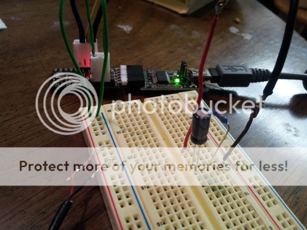
I have the low-pass filter setup as well (on the bread board) and using the PWM I can dial in the required V to the .01 place. Amazing!
The Arduino Pro Mini board however, does NOT have a DAC, so I am only able to use PWM with it. I would have love to run the 08M2 chip, but I'm impatient and was looking for a fast project - ha.
Im looking into an effective means of debouncing the push button currently, and I think I've found the software solution.
[quote]/*
Debounce
Each time the input pin goes from LOW to HIGH (e.g. because of a push-button
press), the output pin is toggled from LOW to HIGH or HIGH to LOW. There's
a minimum delay between toggles to debounce the circuit (i.e. to ignore
noise).
The circuit:
* LED attached from pin 13 to ground
* pushbutton attached from pin 2 to +5V
* 10K resistor attached from pin 2 to ground
* Note: On most Arduino boards, there is already an LED on the board
connected to pin 13, so you don't need any extra components for this example.
created 21 November 2006
by David A. Mellis
modified 30 Aug 2011
by Limor Fried
This example code is in the public domain.
https://www.arduino.cc/en/Tutorial/Debounce
*/
// constants won't change. They're used here to
// set pin numbers:
const int buttonPin = 2; // the number of the pushbutton pin
const int ledPin = 13; // the number of the LED pin
// Variables will change:
int ledState = HIGH; // the current state of the output pin
int buttonState; // the current reading from the input pin
int lastButtonState = LOW; // the previous reading from the input pin
// the following variables are long's because the time, measured in miliseconds,
// will quickly become a bigger number than can be stored in an int.
long lastDebounceTime = 0; // the last time the output pin was toggled
long debounceDelay = 50; // the debounce time; increase if the output flickers
void setup() {
pinMode(buttonPin, INPUT);
pinMode(ledPin, OUTPUT);
}
void loop() {
// read the state of the switch into a local variable:
int reading = digitalRead(buttonPin);
// check to see if you just pressed the button
// (i.e. the input went from LOW to HIGH), and you've waited
// long enough since the last press to ignore any noise:
// If the switch changed, due to noise or pressing:
if (reading != lastButtonState) {
// reset the debouncing timer
lastDebounceTime = millis();
}
if ((millis() - lastDebounceTime) > debounceDelay) {
// whatever the reading is at, it's been there for longer
// than the debounce delay, so take it as the actual current state:
buttonState = reading;
}
// set the LED using the state of the button:
digitalWrite(ledPin, buttonState);
// save the reading. Next time through the loop,
// it'll be the lastButtonState:
lastButtonState = reading;[/quote]
Borrowed from https://arduino.cc/en/Tutorial/Debounce
Posted By: oldspark
Date Posted: May 25, 2012 at 8:17 AM
The Arduino is overkill, but if it works...
What "amazes" me is the cost - the ~$4 8-pin 08M2 plus $2 78L05 regulator (+ 2 resistors) is cheaper and simpler (to construct) than the 14-pin 4017 etc. (That's ignoring the serial interface for programming - ie, a USB to serial if you new PC has no serial port.)
Then that any "circuit change" is merely a program change...
I used to think that using a transistor or 2, or a logic chip etc was easier than using relays for logic. But these PICs make a joke of any design.
Posted By: trbolexis
Date Posted: May 25, 2012 at 9:17 AM
I agree that the adruino is overkill. But at the xost of 13 bucks, and already having the usb to serial interface at home, it was still cost effective and will give the same results. I am going to be stocking up on M2 chips for future projects however.
Posted By: trbolexis
Date Posted: May 25, 2012 at 9:05 PM
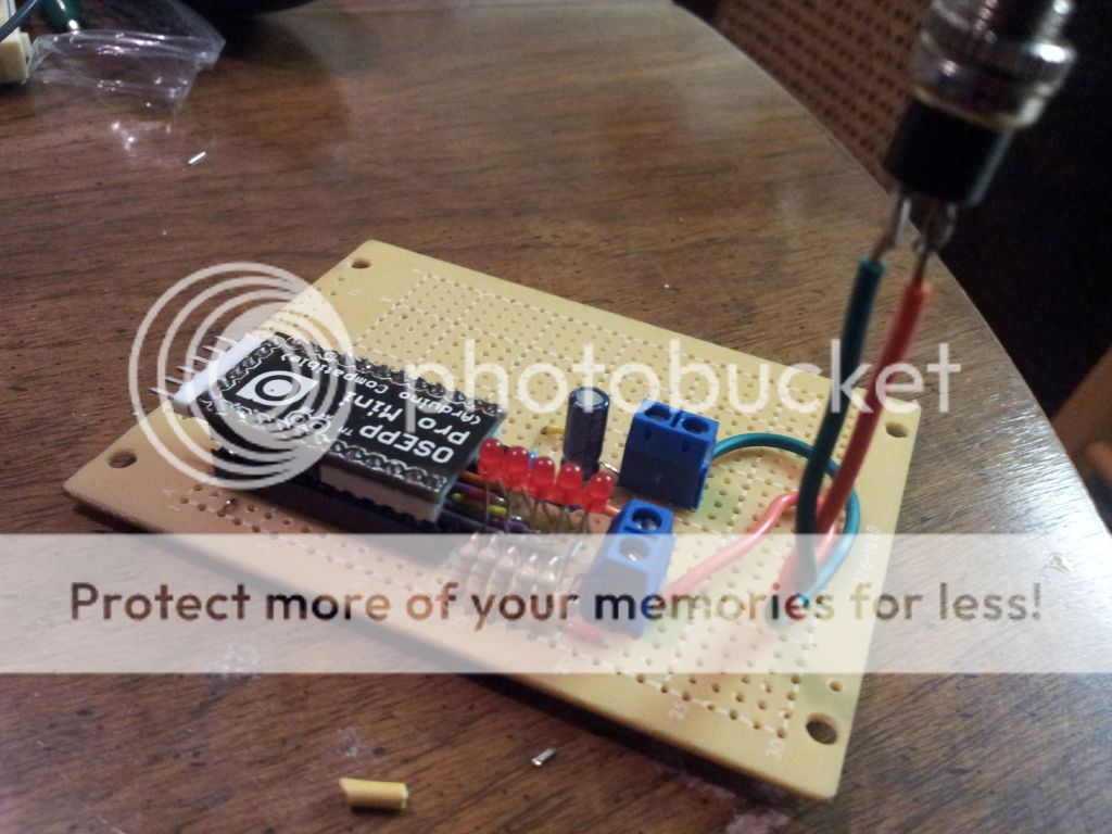
ITS ALIVE! WORKING PERFECTLY! Now I just have to pack it up nicely in a box.
Thanks EVERYONE for all input.
<iframe width="560" height="315" src="https://www.youtube.com/embed/OBY6p-cfoaE" frameallowfullscreen></iframe>
Here is the code for those interested: Please, do NOT use this code for commercial use, without my expressed consent.
[quote]#include <EEPROM.h>;
const int vOutpin = 3;
const int vInpin = 4;
const int led1 = 9;
const int led2 = 8;
const int led3 = 7;
const int led4 = 6;
const int led5 = 5;
const int address = 0;
int mode = 0;
int inputStatus;
void setup () {
Serial.begin(9600);
pinMode(vOutpin,OUTPUT);
pinMode(vInpin, INPUT);
pinMode(led1,OUTPUT);
pinMode(led2, OUTPUT);
pinMode(led3, OUTPUT);
pinMode(led4, OUTPUT);
pinMode(led5, OUTPUT);
}
void loop () {
mode = EEPROM.read(address);
if (mode < 1 && mode > 5) {
EEPROM.write(address, 1);
}
if (mode == 1) {
digitalWrite(led1, HIGH);
analogWrite(vOutpin, 26);
inputStatus = digitalRead(vInpin);
Serial.println(inputStatus);
if (inputStatus == HIGH) {
delay (750);
//digitalWrite(led1, LOW);
EEPROM.write(address, ++mode);
return;
return;
}
}
if (mode == 2) {
digitalWrite(led1, HIGH);
digitalWrite(led2, HIGH);
analogWrite(vOutpin, 77);
inputStatus = digitalRead(vInpin);
Serial.println(inputStatus);
if (inputStatus == HIGH) {
delay (750);
//digitalWrite(led2, LOW);
EEPROM.write(address, ++mode);
return;
return;
}
}
if (mode == 3) {
digitalWrite(led1, HIGH);
digitalWrite(led2, HIGH);
digitalWrite(led3, HIGH);
analogWrite(vOutpin, 128);
inputStatus = digitalRead(vInpin);
Serial.println(inputStatus);
if (inputStatus == HIGH) {
delay (750);
//digitalWrite(led3, LOW);
EEPROM.write(address, ++mode);
return;
return;
}
}
if (mode == 4) {
digitalWrite(led1, HIGH);
digitalWrite(led2, HIGH);
digitalWrite(led3, HIGH);
digitalWrite(led4, HIGH);
analogWrite(vOutpin, 179);
inputStatus = digitalRead(vInpin);
Serial.println(inputStatus);
if (inputStatus == HIGH) {
delay (1100);
//digitalWrite(led4, LOW);
EEPROM.write(address, ++mode);
return;
return;
}
}
if (mode == 5) {
digitalWrite(led1, HIGH);
digitalWrite(led2, HIGH);
digitalWrite(led3, HIGH);
digitalWrite(led4, HIGH);
digitalWrite(led5, HIGH);
analogWrite(vOutpin, 230);
inputStatus = digitalRead(vInpin);
Serial.println(inputStatus);
if (inputStatus == HIGH) {
delay (750);
analogWrite(vOutpin, 26);
digitalWrite(led1, LOW);
delay (250);
digitalWrite(led2, LOW);
delay (250);
digitalWrite(led3, LOW);
delay (250);
digitalWrite(led4, LOW);
delay (250);
digitalWrite(led5, LOW);
delay (250);
EEPROM.write(address, 1);
return;
return;
}
}
}
[/quote]
Thanks again!
Anthony
Posted By: oldspark
Date Posted: May 25, 2012 at 9:23 PM
Typical!
WE effect the solution, and trbolexis clams the IP.
(But it is merely a "please", and I know the :consent" is really a disclaimer...)
And I'm jesting anyway.
Besides, IMO you have the worst part ahead of you - the physicals. The "circuitry" was always the easiest. It was the mounting and boxing etc that took the longest...
Good to see it working. And probably quicker than the discrete solution.
Posted By: trbolexis
Date Posted: May 26, 2012 at 3:56 AM
lol ... hey, is IS IP right? i mean, i do remeber writing the code :P
But you sir, please have free reign to use it as your own. I would have never gone down this path without your guidence, and for that i am greatly appreciative. :)
i have added all comments and refined the code dramatically. With debbuging inclusions and all (not that there is much to debug; more for verbose output to the Serial link for status changes/updates)
Again, i could not thank anyone who helped me with this solution enough. Where can i paypal someone some beer money? lol
Posted By: trbolexis
Date Posted: May 26, 2012 at 3:59 AM
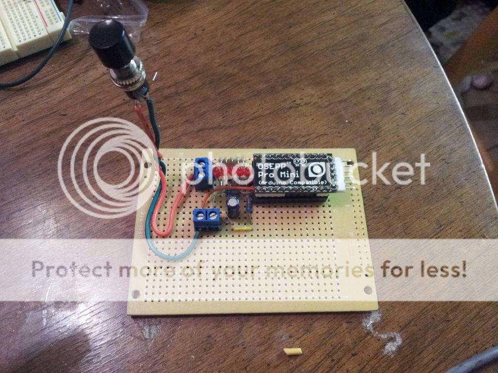 just need a box now!
Posted By: trbolexis
Date Posted: May 26, 2012 at 4:02 AM
Posted By: oldspark
Date Posted: May 26, 2012 at 4:54 AM
IP as in Intellectual Property.
I was jesting, though I reckon I know what you mean.
If nothing else, it'd be nice to get some recognition.
As to "my" 5c** solution that was once posted on a site and now someone is "selling" that solution for AUD$35 (plus $7 postage) - well, I feel happier thinking of it as involving Australians with more cents than sense. [ ** 10c if redundancy or non-polarity/reversibility is desired. ]
Here in Aus your code above would be automatically "Copyrighted" to you having been written by you. But that law varies internationally (and sometimes with "software".)
At least it can't be Patented by anyone.
And then there's the usual issues - new or novel? Arduino is Open Source. You have posted it publicly.
Only a minor change may be needed, and YOU have to prosecute infringers...
I'm rapt because I stated feeling stupid that I suggested the 4017 because I felt the via-diode arrangement wasn't ideal, nor needing the "full" 5V output. (And I didn't do the math to calculate the resistor-matrix required to connect all outputs together.)
So then I commented on using a PIC which is so easy, yet so difficult.
But you made it so easy and so easy. Or so it looks anyhow.
The hard part is the programming (coding), though it's usually not such a big hurdle. Getting the correct RC delays for relay coils without chattering is probably more difficult.
And coding is a threshold thing that when crossed, enables so many things to be done. VIZ - dome- and puddle-light ramp-up and down dimmers, dash & LED dimmers, speed & RPM & temperature etc switches, voltage alarms, and far more complex stuff.
And though you are using an Arduino, if readers could picture that Arduino replaced with an 8-pin PIC chip that does the same thing... (Not that the PIC-08 would be switching all those LEDs, but it will vary the voltage that feeds your EFI boost control...)
Geez - maybe I should solder the 78L05 V-Regs & the programming resistors to my PICs. Then I might start coding... next year...
Posted By: trbolexis
Date Posted: May 26, 2012 at 12:55 PM
The PIC chip as you state is 100% ideal for a project like this. I could not agree more.
I was serious when i asked where i can paypal some beer, coffee, or tea money though :)
Posted By: oldspark
Date Posted: May 26, 2012 at 9:56 PM
Thanks for the sentiment, but the sentiment is reward enough. (Maybe it helps that I found a job last week...?!)
I often find myself in "off world" positions...
EG - on the12volt I may argue against complex relay circuits - ie, IMO it's "easier" or better using electronics for logic.
On other "hi-tech" forums I argue in favor of relays (as opposed to solid-state relays or MOSFETs etc).
Nurds may consider relays too old-tech (I suppose just like wheels, bateries, telephones, and analog ear-canals) whilst relayers may consider a diode or logic gate too complex.
But IMO you have shown how easy it is.
I got the impression you were not "working familiar" with the PICs, yet within hours you had its code together.
We probably both have the advantage of some sort of programming & coding - and yes, that can be a hurdle or threshold experience.
I suspect some readers may get lost with the USB & serial stuff, but if they are on this forum, that's a minor detail. (USB or older serial mouse?)
As for coding, well at least coding "stops" at a certain point, whereas IMO electrical and circuit theory doesn't.
IE - there are a limited number of programming instructions and they have reasonably fixed behavior and outcomes. Brainstorming then uncovers different or more efficient ways of achieving the same or improved outcome.
Compare that to the electrical theory that even the "experienced" are not aware of. And then the (non!) arguments that arise as I recently found out (ie, people allegedly measuring VA for amplifiers or speakers instead of "real" power).
No wonder so many electronic things are being surpassed by programming!
Congrats on the outcome.
Maybe let us know if problems occur, or if you decide to improve the system... (EG - Arduino or PIC senses your repeated FAST throttling so it automatically increments boost since you have selected "auto" mode...)
|