momentary output after ign off
Printed From: the12volt.com
Forum Name: Relays
Forum Discription: Relay Diagrams, SPDT Relays, SPST Relays, DPDT Relays, Latching Relays, etc.
URL: https://www.the12volt.com/installbay/forum_posts.asp?tid=131182
Printed Date: May 07, 2026 at 2:42 AM
Topic: momentary output after ign off
Posted By: oddity
Subject: momentary output after ign off
Date Posted: April 14, 2012 at 12:16 PM
Hello all ... I need a relay to activate a solenoid after turning off the ignition. I would like the relay to not use any power after the pulse.
I was thinking of using the alarm's locking signal for this but would prefer something that worked even if the alarm wasn't used.
I also thought of using the doors lock button but I would need a way of ensuring that it only worked when the ignition was off because my truck locks automatically when I go over 20mph and i dont want the solenoid to work while driving..only parked. But how do I do that?
I would prefer something that worked automatically when i turned of the ignition and would remain passive.
Any Ideas? I could really use some help with this....Thanks
Replies:
Posted By: itsyuk
Date Posted: April 14, 2012 at 9:52 PM
please explain in more detail what you are trying to accomplish.
------------- yuk
quiet rural missouri, near KC.
If your system moves you physically and not emotionally, you have wasted your money.
Posted By: oddity
Date Posted: April 15, 2012 at 5:20 AM
I need to send a momentary pulse to a solenoid after i turn off the ignition and not have the relay draw current after the momentary pulse.
Posted By: howie ll
Date Posted: April 15, 2012 at 6:45 AM
Go to the relay section on this site look for constant neg input and momentary output, use your ignition wire to terminal 85 via resistor and capacitor.
-------------
Amateurs assume, don't test and have problems; pros test first. I am not a free install service.
Read the installation manual, do a search here or online for your vehicle wiring before posting.
Posted By: oddity
Date Posted: April 15, 2012 at 8:18 AM
Thank you for your response
I looked under the link "Relay Diagrams - Quick Reference" (Last Updated: 5/7/2011) there was 4 diagrams for constant to momentary and 2 were neg input ,but all showed a neg at pin 85 where you said i should connect my ignition. Then i remembered this post i came across--https://www.the12volt.com/installbay/forum_posts.asp?tid=60614&tpn=1&PN=1
it looks like the neg to neg diagram in the quick ref except the coil polarity and capacitor are reversed. looks like it draws current momentarily when ign is first turned on and releases the pulse with ign off and draws no further current.. Is this correct?
Thanks again for your help
Posted By: howie ll
Date Posted: April 15, 2012 at 8:23 AM
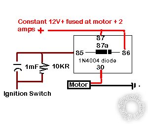
The one I was thinking of showed a neg switch at 85, this is the ignition which will show NEG when turned off. Please try to understand that a POS ignition wire shows NEG when you turn it off. Test if you don't believe me but you will be wrong.
Gives you a POS output at 30.
85 is conventionally (ISO wiring pin convention) the NEG of the coil, 86 the POS.
-------------
Amateurs assume, don't test and have problems; pros test first. I am not a free install service.
Read the installation manual, do a search here or online for your vehicle wiring before posting.
Posted By: howie ll
Date Posted: April 15, 2012 at 8:45 AM
See if you understand it better now.
constant_to_pulse.bmp------------- Amateurs assume, don't test and have problems; pros test first. I am not a free install service.
Read the installation manual, do a search here or online for your vehicle wiring before posting.
Posted By: oddity
Date Posted: April 15, 2012 at 9:42 AM
thank's for the diagram. i did not know that the pos ign wire showed neg in the off position...i thought it became an open circuit.
Does the relay draw a small amount of current throught the 10k resistor while the ign is off?
Posted By: howie ll
Date Posted: April 15, 2012 at 9:49 AM
How can it on a NEG ground vehicle, also don't forget the diode across the relay, that acts as a current block.
-------------
Amateurs assume, don't test and have problems; pros test first. I am not a free install service.
Read the installation manual, do a search here or online for your vehicle wiring before posting.
Posted By: oddity
Date Posted: April 15, 2012 at 10:27 AM
I'm trying to fully understand this... What stops 1ma (12/10k) of current from going from the constant 12v source through the coil and resistor to the now negative ign wire ?
Posted By: howie ll
Date Posted: April 15, 2012 at 11:20 AM
The bloody diode. I've already explained that.
-------------
Amateurs assume, don't test and have problems; pros test first. I am not a free install service.
Read the installation manual, do a search here or online for your vehicle wiring before posting.
Posted By: oddity
Date Posted: April 15, 2012 at 11:31 AM
In the diagram you supplied the diode is in parallel with the coil how does it stop current from going through both paths?
Posted By: howie ll
Date Posted: April 15, 2012 at 11:38 AM
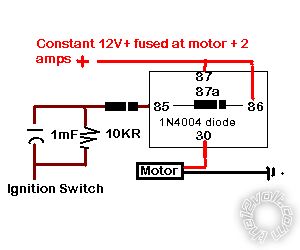
A valid question if you know nothing about relays but believe me it does. If you're not sure place ANOTHER 1N4004 in line between the cap and the resistor before 85, band away from relay that's another variation, maybe I didn't modify the original enough.
Look now:- 784_constant_to_pulse.bmp------------- Amateurs assume, don't test and have problems; pros test first. I am not a free install service.
Read the installation manual, do a search here or online for your vehicle wiring before posting.
Posted By: oldspark
Date Posted: April 15, 2012 at 8:45 PM
That's the problem with "physical" diagrams.
Forgive me if I am pre-coffee confused, but don'tcha hate these Juniors that are right?
Good onya oddity! Thanks for questioning and clearly stating your understanding... er, I mean confusion. 
(I usually draw "circuit" diagrams.)
If drawn showing the relay coil, it is more obvious that without the extra series diode, there is always current flowing thru the coil & 10k resistor (ie, ~12V/10k =1.2mA).
Of course NOW the problem is that the relay will never turn on because of the blocking diode.
Maybe it is a situation where the circuit should be reversed - ie, +12V IGN thru he diode to #86 (#85 to GND) and capacitor (its -ve to GND).
Theory: IGN +12V turns on the relay charges the cap. When off, the diode prevents the cap discharging thru IGN +12V circuits (which is effectively GND). The cap discharged thru the relay coil, thereby holding it on for a while.
The "time constant" tis RC (which is when the RC voltage reaches ~67% of its target, ie, from ~+12V down to GND = 0V in this case) where the "R" is the resistance of the coil.
Hence if ~60R (Ohms), C = t/60, eg, ~0.15F (150,000uF) for ~10 seconds. (Assuming the relay drops out at about 67% down (~4V) which is probably a bit low, but t=RC is still a good approximation.)
The latter also shows why I don't like RC delays direct on relay coils (too high a current (meaning too low a resistance) means a BIG cap).
Instead, Id rather a transistor "buffer" so the RC handles the transistor's Base current which is far less than the relay coils.
But I'll leave that for later if needed, and assuming I'm correct about that undesired 1.2mA constant leak.
Howie, do you concur?
BTW - the original "reverse biased" diode between 85 & 86 is merely for suppression of the coil's "off" voltage spike.
Meanwhile, coffee and breakfast...
Posted By: howie ll
Date Posted: April 16, 2012 at 2:51 AM
Oops red faced he redoes the second diagram, yes I did realise about 3:30 this a.m. but thought the better of getting out of bed 
Revised:- A5B_constant_to_pulse.bmp------------- Amateurs assume, don't test and have problems; pros test first. I am not a free install service.
Read the installation manual, do a search here or online for your vehicle wiring before posting.
Posted By: oldspark
Date Posted: April 16, 2012 at 5:14 AM
And I missed that it was to be a pulse output.
I was describing a relay that held on for a period of time...
This is a typical specialized application a differentiator (IGN off) and integrator (time delay), and that can't be done with "passive" components. Well, not easily anyway.
Posted By: dualsport
Date Posted: June 10, 2012 at 10:14 PM
Drew this up back in 2002, but it does what you're looking for; you'll only need the top half of the circuit. Ignore the bottom.

There should be negligible current draw after the pulse is delivered on ignition shutdown.
You can tweak the component values as needed to change the pulse output duration if you want.
|