relay spike?
Printed From: the12volt.com
Forum Name: Relays
Forum Discription: Relay Diagrams, SPDT Relays, SPST Relays, DPDT Relays, Latching Relays, etc.
URL: https://www.the12volt.com/installbay/forum_posts.asp?tid=131849
Printed Date: May 08, 2026 at 8:58 AM
Topic: relay spike?
Posted By: tinecidy627
Subject: relay spike?
Date Posted: July 19, 2012 at 3:26 AM
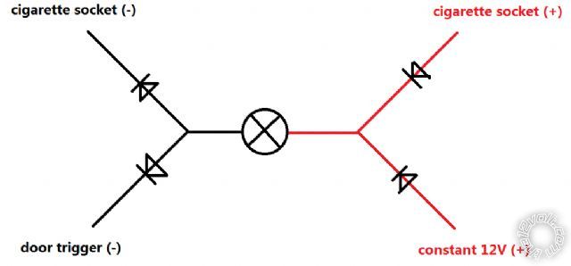
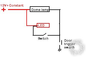
Hi everyone, I have some problem in the circuit using this relay. So basically, it is some LED lights that I want them on when the door is open, also can be turned on/off with a switch that connected to the 12v cigarette socket. So as shown in the figure above, the top half is the socket line, while the bottom half is the door trigger line.
I used diodes to isolate the two lines, as shown in the figure.
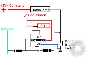
However, I figured out that in the cigarette socket line, the +12v is controlled by the ignition, while the (-) is always connected to chassis ground. While in the door trigger line, the +12V is constant, and the (-) is provided only when any door is opened. So the situation becomes the second figure:
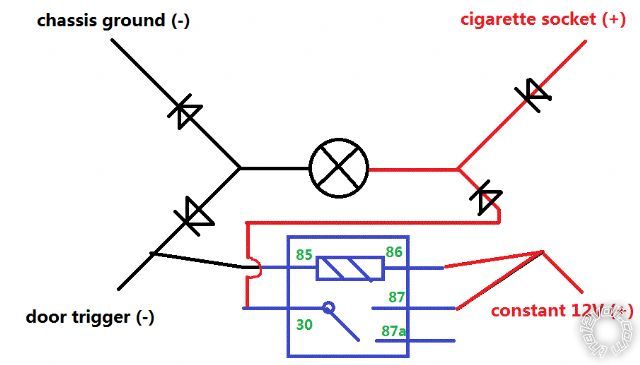
As you can see, since one line has constant +12v, while the other has constant ground, the LED is always on. So I designed to add a relay in it, as shown above. So when the door trigger (-) is not present, the relay cuts the constant +12v, so problem solved.
However, I found that every time when the door is shut, that is to say when the relay input is cut, the relay makes a noise. Is that called spike I guess? I tried to switch the 85 and 86, now which 85-ground 86-12V, but the spike is still there. Why?
And BTW, if there is no way to kill the spike noise in the current design, could anyone come up with a better solution?
Many thanks!! Really want to get rid of the noise ASAP.
Replies:
Posted By: tinecidy627
Date Posted: July 19, 2012 at 3:28 AM
I also tried to connect 87a to chassis ground constantly, but won't kill the spike problem. I heard may be a diode parallel to the relay may work?
Posted By: howie ll
Date Posted: July 19, 2012 at 6:34 AM
Remove the two diodes on the power lines, you will blow them as soon as you insert the lighter (15amps).
Place a 1N4004 diode across the relay coil, band to 86 or this:-
led_dome_light.bmp
You don't need relays, diodes or a cig. lighter.
Only resistor(s) if the the LED's aren't 12V.
In fact you could incorporate a 528t timer instead of the relay and make it fully auto with ignition on cut out.
This version will shut down when door shut OR ignition turned on.
The switch on the LED 12V+ line is optional.
Relay is a standard automotive or even 5amp PCB relay, diodes are 1N4004.
2DE_led_dome_light.bmp------------- Amateurs assume, don't test and have problems; pros test first. I am not a free install service.
Read the installation manual, do a search here or online for your vehicle wiring before posting.
Posted By: tinecidy627
Date Posted: July 19, 2012 at 3:14 PM
Thank you, howie.
Actually it's not a "LED", but some commercial interior light kit with cigarette lighter socket. I do want to keep the socket plug which has a nice switch on it, that's why I bothered to design the figures. I'm not sure that since it's not a cig lighter, it should not be hight current as 15A, right?
I'll follow yours to remove the diodes and across one to the relay. But is there any clear explanations for why my current design produces a spike? Thanks a lot.
Posted By: howie ll
Date Posted: July 19, 2012 at 4:20 PM
No diode across the coil.
Anything with a power outlet should be AT LEAST 10amps.
-------------
Amateurs assume, don't test and have problems; pros test first. I am not a free install service.
Read the installation manual, do a search here or online for your vehicle wiring before posting.
Posted By: tinecidy627
Date Posted: July 19, 2012 at 4:26 PM
OK. Do you mean that I have to give up the current design to kill the spike noise?
Posted By: howie ll
Date Posted: July 19, 2012 at 4:28 PM
No, just a diode across the coil in your second diagram.
-------------
Amateurs assume, don't test and have problems; pros test first. I am not a free install service.
Read the installation manual, do a search here or online for your vehicle wiring before posting.
Posted By: tinecidy627
Date Posted: July 19, 2012 at 7:20 PM
tried that, doesn't work. double checked 86-t0-12v, 85-to-gnd, diode strip towards 86.
Posted By: tinecidy627
Date Posted: July 19, 2012 at 7:23 PM
single pole double throw relay (I guess)
AGT 12V 30/40A 14VDC MAH-112-C-1
Posted By: tinecidy627
Date Posted: July 19, 2012 at 7:31 PM
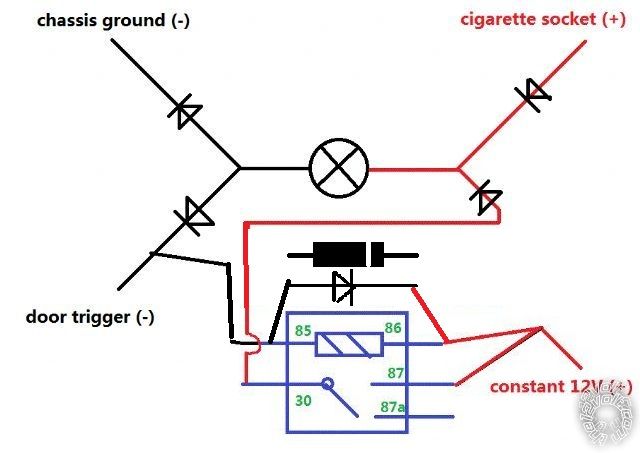
just want to make sure, after crossing a diode on the coil, it looks like this.
double checked that diode is 1N4004, used one to cross. (may be try multiple?)
Posted By: howie ll
Date Posted: July 20, 2012 at 2:03 AM
Then use my second diagram.
-------------
Amateurs assume, don't test and have problems; pros test first. I am not a free install service.
Read the installation manual, do a search here or online for your vehicle wiring before posting.
Posted By: t&t tech
Date Posted: August 01, 2012 at 7:16 AM
What type of noise do you get? Is it a buzzing or a solid click.
Posted By: tinecidy627
Date Posted: August 10, 2012 at 5:59 PM
Thanks for replying. It's buzzing, lasts about 1 second. I know a click should be proper function as disconnection. I tried diodes and they don't work. I'm considering if a resistance would bring the instant current down.
Posted By: i am an idiot
Date Posted: August 10, 2012 at 9:26 PM
You need a diode and a capacitor. I will look for the thread with the instructions.
Posted By: i am an idiot
Date Posted: August 10, 2012 at 9:29 PM
Posted By: tinecidy627
Date Posted: August 11, 2012 at 10:20 PM
thanks a lot man! but i didn't get it completely. so a capacitor cross the relay coil, and the diodes? in series and what (with the capacitor may be?)? i don't quite understand how to apply to my case. many thanks!
Posted By: i am an idiot
Date Posted: August 12, 2012 at 1:06 PM
Is the relay supplied with constant positive voltage, or constant ground?
Posted By: tinecidy627
Date Posted: August 14, 2012 at 9:43 PM
Yes. Constant +12v connected, conditional ground connected. Is this the problem? Thx
Posted By: i am an idiot
Date Posted: August 14, 2012 at 11:25 PM
Not a problem. I just needed to know which way you had it so I can pinpoint the appropriate picture for you.
Posted By: i am an idiot
Date Posted: August 14, 2012 at 11:32 PM
Posted By: i am an idiot
Date Posted: August 14, 2012 at 11:35 PM
You may or may not have 30, 87, and 87A wired correctly. That was on the picture from the original post.
Posted By: tinecidy627
Date Posted: August 18, 2012 at 12:28 AM
Thanks a lot man!!! So I need a 1000 uF 25V capacitor.
Now I have 85 to negative trigger with a diode on, 86 to +12v feed, 87 to +12v input, 30 to the light, 87a to nothing.
So I guess the diode on 85 is really necessary, hah? I will try after got the capacitor~~
|