delay off relay
Printed From: the12volt.com
Forum Name: Relays
Forum Discription: Relay Diagrams, SPDT Relays, SPST Relays, DPDT Relays, Latching Relays, etc.
URL: https://www.the12volt.com/installbay/forum_posts.asp?tid=132026
Printed Date: March 17, 2026 at 6:29 AM
Topic: delay off relay
Posted By: jmv5171195
Subject: delay off relay
Date Posted: August 17, 2012 at 7:46 PM
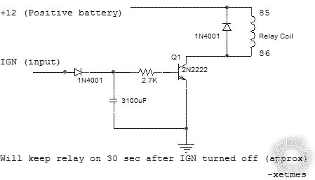
Saw this diagram on here in another thread and was wondering if I could replace the Capacitor in this diagram with a Potentiometer to give me the abilities to change the delay by just using the switch.Is this possible?
Replies:
Posted By: oldspark
Date Posted: August 18, 2012 at 12:29 AM
No, you replace the resistor with a pot.
Posted By: jmv5171195
Date Posted: August 18, 2012 at 8:47 AM
Which resistor would I replace the 10K or the 33K? Could I make this without the push button switch. Also how does the relay wire up as in where does my output to the light go?
Thank you for the help so far!
Posted By: oldspark
Date Posted: August 18, 2012 at 10:10 AM
The 33k.
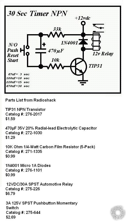
But that may not be the the circuit you want.
It's a "pulse" timer.
When first powered up, it turns the relay on for the delay time (ie, ~30 seconds as determined by the 33k & cap).
Thereafter, pressing the switch turns it on again and it turns off !30 seconds after opening (letting go) of the switch.
The relay contacts (top RHS of the diagram) would control your light.
Posted By: jmv5171195
Date Posted: August 18, 2012 at 10:35 AM
Ah I see. I don't think this is going to work then. What I'm looking for is a circuit that powers up for a set time by a negative trigger. The application is for my remote start that isn't equipped with illuminated entry. When the remote start receives a signal to lock or unlock, the circuit is activated and lights the dome light up for the specified time period.
Posted By: oldspark
Date Posted: August 18, 2012 at 11:11 AM
Have a look at the 555 timer in monostable mode. Pin #2 is a -ve trigger input (as I recall).
The 555 consumes 10mA in standby mode, though the CMOS equivalent (the 7555?) should consume far less.
There is also the possibility of using a PICAXE 08 - an 8 pin chip, plus a 5V regulator, 2 programming resistors and an output buffer (eg, 2 resistors & a transistor, or a MOSFET to drive a relay or whatever) plus whatever input is required.
Though that has the programming overhead (ie, a PC serial port), the advantage is its fully programmable possibilities using up to ~5 inputs and up to ~5 output.
Posted By: jmv5171195
Date Posted: August 18, 2012 at 1:13 PM
The PICAXE 08 sounds real cool but a little overkill for just a dome light. Would the monostable mode of this chip work?
Once again thank you very much for the help, my knowledge of micro controllers are little. 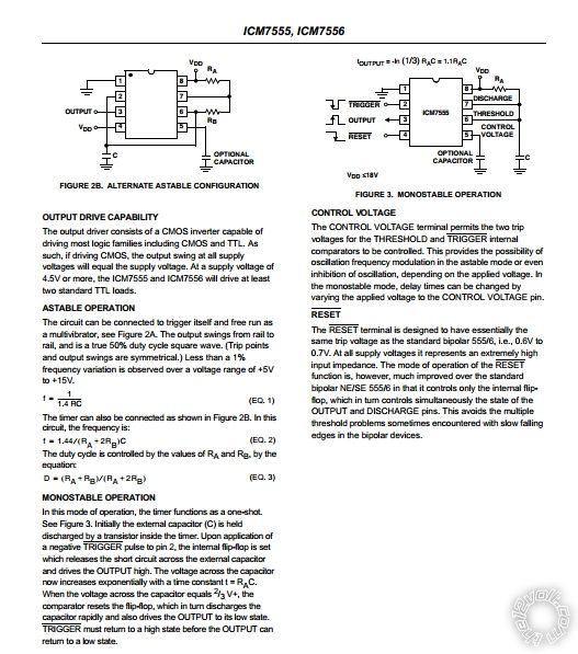
Posted By: oldspark
Date Posted: August 18, 2012 at 7:47 PM
Yes, that's the 555 albeit the CMOS version (lower power draw).
You should find lots of circuits on the web to confirm your design.
The delay time is something like R x C.
It may only output 200mA so a transistor etc may be needed.
Beware of CMOS handling if using the 7555 (no static electricity).
It should handle normal vehicle voltages but protection may be worthwhile.
Usually the +V (+12V) is via a diode (IN4004etc) for polarity protection, and a low-value resistor followed by a Zenor diode (say ~15V)to pin 8 (& 4).
The output load (eg relay) can be driven from the raw +12V if a ground switched output transistor (or MOSFET) is used. Hence the +12V series resistor only has to carry the 555 operating current (ie, 10-20mA; less for 7555) without too high a voltage drop. (Driving the 200mA output means a 10x to 20x smaller resistor with a higher wattage rating, and a Zenor rating to suit.)
Protect the input as well. Usually thru a resistor and "reverse connected" diodes to both +V & 0V (GND).
And usually a pull-up resistor (if pin 2) to keep un-triggered until the -ve pulse.
Posted By: jmv5171195
Date Posted: August 18, 2012 at 8:39 PM
I could live with having the output load run 200mA and just have it drive a relay.My 12v input is going to pin 8 and 4 correct?The more I reread your instructions the more I start to pick up.Thanks yet again!
Posted By: oldspark
Date Posted: August 19, 2012 at 5:10 AM
Yep. Follow the 555 info. Pin #1 is GND, pin #8 is +V but #4 (Reset) is usually tied to +V (#8) to avoid false resets.
See technologystudent-elec1-5554.htm to confirm your circuit.
Your relay would be connected in place of the buzzer of the 555 drives the relay direct (but omit the buzzer's diode to +V and place it across the relay coil as shown in the 2nd relay diagram).
Else use the relay driver circuit output if using a transistor as per the 2nd diagram. Note that then the relay coil is connected from +V (#86) with it's -ve end (#85) to the transistor output (its Collector).
The " Relay Toggle Circuit Using a 556 Timer" down the page at bowdenshobbycircuits-page9 may be better for its transistor details, though I think I prefer the previous links wiring for pin #2 etc.
Another good 555 reference is kpsec.freeuk-555timer.
Posted By: hotwaterwizard
Date Posted: August 25, 2012 at 11:55 PM
I have Used my circuit for many applications and I do think it will work.
------------- John DeRosa (Hotwaterwizard)
Stockton California
When in doubt, try it out !
Posted By: howie ll
Date Posted: August 26, 2012 at 8:10 AM
Or use a DEI 528t or 611t both almost as cheap as buying the parts or get an interior (dome) light delay kit from Velleman.
Ad yes a pulse timer from the unlock cycle is exactly what our poster requires.
-------------
Amateurs assume, don't test and have problems; pros test first. I am not a free install service.
Read the installation manual, do a search here or online for your vehicle wiring before posting.
Posted By: howie ll
Date Posted: August 26, 2012 at 8:25 AM
Or Velleman K3500 kit.
-------------
Amateurs assume, don't test and have problems; pros test first. I am not a free install service.
Read the installation manual, do a search here or online for your vehicle wiring before posting.
Posted By: jmv5171195
Date Posted: August 26, 2012 at 9:43 AM
The Velleman Kit looks ideal. I liked the 555 timer idea but i can't get it to work right. The two relay ideas seem feasible they just seem a little bulky.
Posted By: jagadeesh
Date Posted: September 06, 2012 at 3:15 AM
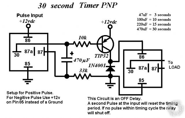
Thanks for 12 volt.com and team member hotwaterwizard for OFF DELAY CIRCUIT, I am going to use the circuit on my diesel car for remote start and I also want to include antigrind feature, but my confusion is I want wait to start relay like 528T, but the relay circuit is shown as OFF DELAY, I need ON DELAY CIRCUIT, also I want to learn the difference between NPN and PNP applications. I feel very happy to be with you for discussing though I am not a professional, but still I can make things what I want with your kind help. The cost of shipping is tripled if I am to go for 528T. Hats off to your help. My requirement is for positive pulse.
Posted By: howie ll
Date Posted: September 06, 2012 at 3:26 AM
All reputable remote starts have a built in fixed or variable time diesel delay.
The 528t can be configured for delay on OR off, POS OR NEG trigger.
-------------
Amateurs assume, don't test and have problems; pros test first. I am not a free install service.
Read the installation manual, do a search here or online for your vehicle wiring before posting.
Posted By: hotwaterwizard
Date Posted: September 06, 2012 at 10:33 PM
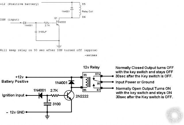
For on Delay use 87a for the load instead of 87 on all of the circuits.
A larger capacitor will change the durration to longer time period. also a 50k variable resistor instead of the 33k resistor will make it settable for shorter or longer periods. ------------- John DeRosa (Hotwaterwizard)
Stockton California
When in doubt, try it out !
Posted By: jagadeesh
Date Posted: September 08, 2012 at 10:03 AM
Please show some light on the circuit showing TIP 31 NPN and TIP 32 PNP, please provide description on both circuits.I am to make circuit at any cost and come back to you. But I am going to simulate the things by putting dummy load like 35 watts bulb and the make circuit and adjust the delay to my requirements, but first I want little understanding for wait to start relay application-
1) when I press the remote start, first pulse will start ignition lights and later by using the earlier pulse received by the delay relay which is between starter and out pulse -make delay of 30 seconds and then shots a brief positive pulse to stater, which starts the vehicle.
As I said earlier I will set up things and start to do practicals.
I am already having autocop basic alarm system to which I am going add etc remote to start the vehicle.
Thanks for providing tips to go ahead, I love you people.
Posted By: hotwaterwizard
Date Posted: September 08, 2012 at 1:23 PM
almost any transistor will do the job aslong as it can handle the current of the relay coil.
I have actually used a 2N2222a for the circuit with a small relay. ------------- John DeRosa (Hotwaterwizard)
Stockton California
When in doubt, try it out !
Posted By: hotwaterwizard
Date Posted: September 08, 2012 at 2:18 PM
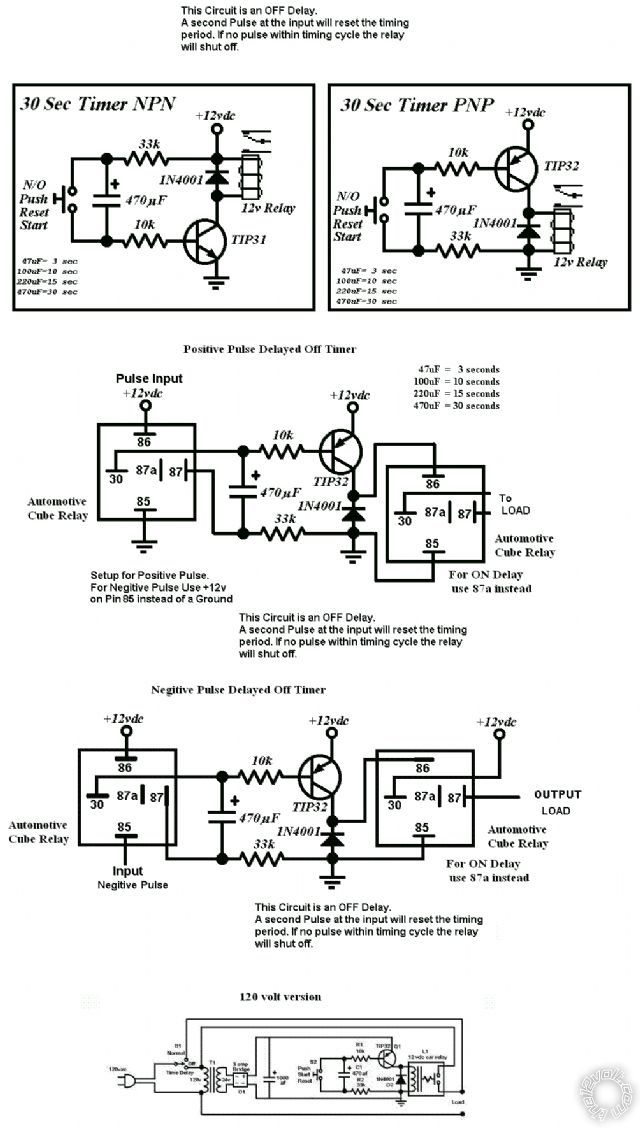
Look at this circuit!
I redrew the circuit so you could understand it.
------------- John DeRosa (Hotwaterwizard)
Stockton California
When in doubt, try it out !
Posted By: jagadeesh
Date Posted: September 10, 2012 at 8:44 AM
Dear John DeRosa, thank you for your precious time, Now I am able to understand better about the circuit especially redrawn one, mentioning in detail, as to how the relay behaves at the far right side of the relay coil 85 and 86 terminals. Now I will do the circuit and come back with some positive result.
with regards,
Jagadeesh
Posted By: jagadeesh
Date Posted: September 10, 2012 at 9:52 AM
At the ignition input 12 volt of the redrawn circuit, the diode is in reversed placement compared to the original sketch, may I know the reason for this, sorry for double post, delayed understanding after going through the circuit in detail it came to my observation -the question is-if ignition input is fed, 12 volt voltage will be limited at the diode point -1N4001. I am correct- if not correct me.
Posted By: hotwaterwizard
Date Posted: September 10, 2012 at 2:19 PM
Oops I screwed up the diode should be reversed as in the original diagram
-------------
John DeRosa (Hotwaterwizard)
Stockton California
When in doubt, try it out !
Posted By: jagadeesh
Date Posted: September 11, 2012 at 11:59 AM
Thanks for diode information,I will correct my self in the redrawn circuit- only the diode portion, now i am happy, meanwhile, I have brought the automative relays and the electronics components, based on your circuit I will build the circuit for- 10 second wait to start circuit when positive pulse is received the circuit delays the positive for about 10 second and then triggers the positive pulse to starter, after triggering the circuit goes off. this is the plan I have in my mind. I will take the help of neighbor children to identify the resistor color code as I have color blindness and then use the color to codify, start doing practicals by applying the load as 35 watts bulb presuming the bulb as starter motor.I don't need exact 10 second, 2 to 3 second does not make difference to me,after getting success I will mention what went well, once again thanks for your precious time, I am very grateful to you, you saved be the shipping cost of 528T.
Posted By: howie ll
Date Posted: September 11, 2012 at 1:30 PM
Why do I have the feeling that you are trying to build a home made remote start?
If so I must strongly caution you against building it, too dangerous.
Where are your inhibitors, engine tach to cease starter grinding?
Over-revving?
What stops it starting in gear if a manual?
Someone stealing the vehicle?
Hood (bonnet) being opened?
And on a time and cost basis far cheaper inc. shipping to buy and install a ready made from a known manufacturer.
I made the last point because ALL reputable product includes a wait to start feature for diesels.
-------------
Amateurs assume, don't test and have problems; pros test first. I am not a free install service.
Read the installation manual, do a search here or online for your vehicle wiring before posting.
Posted By: jagadeesh
Date Posted: September 12, 2012 at 4:07 AM
I have fixed the remote starter in petrol cars and the safety feature I would use handbrake earthing, the negative voltage feeds the starter to come otherwise it won't. Presently I am making use of the another remote start module to diesel car which basically required the wait to start, so only wait to start feature is home made and main module is from xenos manufacturer. I am not competent to create home made remote starter main module with remote transmitters which requires extensive knowledge,in that case I better purchase as you say, I agree with you that purchasing a module is far better but few changes can be modded and my knowledge is very limited. I am ardent follower of safety, safety is first.Thanks for your concern I understand you what the safety means not only to us, but on the other side also.
Posted By: oldspark
Date Posted: September 12, 2012 at 4:28 AM
A remote start with only a handbrake safeguard?
Oh dear....
Howard - we have a problem!
Posted By: jagadeesh
Date Posted: September 12, 2012 at 8:56 AM
when you don't apply hand brake no negative signal is received at the starter, so safety is assured, antigrind /brake/tach sense /bonnet all these things are not applicable as long as I take care of safety issue.
Posted By: howie ll
Date Posted: September 12, 2012 at 12:17 PM
And every REPUTABLE manufacturer allows for these things plus built in wait to start for diesels. Methinks we'll be asked next why this R/S requires a connection to the oil pressure switch.
You know what my next comment will be don't you Peter.
Foot brake?
Bonnet switch interrupts?
-------------
Amateurs assume, don't test and have problems; pros test first. I am not a free install service.
Read the installation manual, do a search here or online for your vehicle wiring before posting.
Posted By: oldspark
Date Posted: September 12, 2012 at 4:22 PM
jagadeesh wrote:
...so safety is assured, antigrind /brake/tach sense /bonnet all these things are not applicable as long as I take care of safety issue.
jagadeesh, it is obvious you do not understand the safety issues involved.
But you have been warned or advised.
I'm staying out of this one.
Whilst I love seeing negligence sued, I get upset at injury and deaths that should have been avoided.
Unwatching this topic.
Posted By: howie ll
Date Posted: September 12, 2012 at 5:38 PM
X2 I wouldn't even get involved without all those safety cut-outs and what chance the vehicle is an auto in India?
Ever seen a manual left in gear down hill with a remote start installed without safeguards, even with the hand brake engaged boy is that vehicle going to move.
How many times have we driven off with the handbrake engaged?
-------------
Amateurs assume, don't test and have problems; pros test first. I am not a free install service.
Read the installation manual, do a search here or online for your vehicle wiring before posting.
Posted By: jagadeesh
Date Posted: September 13, 2012 at 2:58 AM
By -oldspark jagadeesh, it is obvious you do not understand the safety issues involved.
But you have been warned or advised.
I'm staying out of this one.
Whilst I love seeing negligence sued, I get upset at injury and deaths that should have been avoided.
Unwatching this topic.
By- Howie II X2 I wouldn't even get involved without all those safety cut-outs and what chance the vehicle is an auto in India?
Ever seen a manual left in gear down hill with a remote start installed without safeguards, even with the hand brake engaged boy is that vehicle going to move.
How many times have we driven off with the handbrake engaged?
Dear gentlemen- I appreciate your true concern towards safety,I drop the idea of meddling with connection to remote starter - use the delayed on circuit for my car A/C to extended delayed ON as it gives longevity to my battery in order to avoid immediate switching on the A/C after parking for long time- 15days or so, so that battery gets charged by the alternator and my timer prevents A/C being on putting etc load in the initial stage itself. Meanwhile I hate to be sued for negligence from my side and also hate causing injury to the public.
Once thanks for your kind advice for opposition to remote start due to safety issue.
with regards-jagadeesh
Posted By: howie ll
Date Posted: September 13, 2012 at 3:30 AM
Completely moot, all AC systems, even aftermarket have a built in time delay, the AC will not start until engine is already running so your last comment is unfortunately also irrelevant, it won't affect the battery.
-------------
Amateurs assume, don't test and have problems; pros test first. I am not a free install service.
Read the installation manual, do a search here or online for your vehicle wiring before posting.
Posted By: howie ll
Date Posted: September 13, 2012 at 3:49 AM
P.S. I've had current Rover 75 Tourer since April.
Before that it was sitting around untouched for a year with the battery disconnected.
Battery is a Yuasa large size, BMW 5 series, Mercedes etc.
Jump started, driven 10 miles then left on a trickle for 3 days.
This has full climate control AC which also incorporates front and rear heated rear windows.
Plus power locks and windows, heated seats etc.
Naturally I installed a full remote start alarm system, I'm now doing 2-300 miles per week.
Weather depending the AC is left on the night before and automatically comes on with the remote start.
I've NEVER had battery problems.
Also and Oldspark will verify this, if you're at sea level and don't make short journeys (less than 20 miles) your battery if maintained should last about 7 years in India's climate.
-------------
Amateurs assume, don't test and have problems; pros test first. I am not a free install service.
Read the installation manual, do a search here or online for your vehicle wiring before posting.
Posted By: howie ll
Date Posted: September 13, 2012 at 3:54 AM
It's short stop start journeys, cold weather and lack of maintaining (not checking levels if not sealed, dirty corroded terminals bad alternators and earth and power connections etc.)which kill batteries.
Scandinavia, Scotland Russia, Canada, Northern US and Alaska, 2 years.
Temperate climates 5 years.
Tropical and Sub-Tropical 7 years.
-------------
Amateurs assume, don't test and have problems; pros test first. I am not a free install service.
Read the installation manual, do a search here or online for your vehicle wiring before posting.
Posted By: jagadeesh
Date Posted: September 13, 2012 at 11:47 AM
when we purchased new diesel car the battery's life came for 3 years, now we have brought amron maintenance free sealed battery, since I face parking problem I use 800 maruti a hatch back petrol car known for simplicity, the disel one is tata indigo lx (disel) a cheapest car one can buy in India, it came with a central lock, but when we bargained for remote they added a remote for central lock which is basic by name piranha with short antenna to pull to get range which is from autocop, however no reverse beep or flashing of lights,i would have loved if the same would have been there, so far i never faced problem with central lock, regarding A/C when I switch on blower which has 4 speed manual option, only blower will be ON, but to switch on A/C the vehicle should be in running so no question built in time delay as I have observed the car A/C after seeing your post, so I feel I am not completely moot. You can just google for tata indigo, quality is not to upto the mark, but a decent one which is turbo charged tdi, no sudden pickup, have to wait till RPM reaches max to overtake a vehicle. Regarding battery life average is 3 years. Sorry for off topic just a moment of sharing experiences.
|