time delay relay for horns
Printed From: the12volt.com
Forum Name: Relays
Forum Discription: Relay Diagrams, SPDT Relays, SPST Relays, DPDT Relays, Latching Relays, etc.
URL: https://www.the12volt.com/installbay/forum_posts.asp?tid=132425
Printed Date: March 18, 2026 at 11:34 AM
Topic: time delay relay for horns
Posted By: bvbull200
Subject: time delay relay for horns
Date Posted: October 19, 2012 at 9:43 AM
Hello all. I did some reading on this forum hoping to answer a question I had and came across this thread:
https://www.the12volt.com/installbay/forum_posts.asp?tid=57690&tpn=1&PN=1
It is 7 years old, but I was hoping to revive it as it is precisely what I'd like to do. Much to my chagrin, it is closed, though.
I'd like to add a Wolo Model 417 horn to my vehicle. That said, my horn is also an indicator for when I lock my doors with keyless entry, giving me a short beep to let me know that they are locked. I'd like to use my factory horn for that beep and the upgraded horns when I actually press the steering wheel to honk in traffic.
The thread I linked seems to suggest just that, but I'm a bit new at relays and was hoping to get some information as to just how that would be wired up.
2010 Mazdaspeed3 if it makes a difference.
Thanks in advance. ------------- I'm a novice. Go easy on me.
Replies:
Posted By: shortcircuit161
Date Posted: October 19, 2012 at 10:14 AM
If you are looking to have the Wolo horn work only when the ignition is on, you can wire a standard relay to run the Wolo only when the car is on. All other times, (on ACC only or car off) the factory horn would be engaged.
Relay setup
Pin 86 - horn (-) trigger wire
Pin 85 - goes to ignition wire
Pin 87 - connect to 12v Constant
Pin 87a - not used
Pin 30 - to (+) terminal on Wolo compressor
Horn Trigger blue - BCM, blue 24 pin plug (2), pin U
Notes: The BCM (Body Control Module) is above the driver kick.
Ignition blue + ignition switch, 8 pin plug, pin A
Notes: On vehicles with Smart Key, it is at the relay block, 6 pin plug, pin B. The relay block is to the left of the steering column.
12volts orange (40A) + ignition switch, 8 pin plug, pin H
Notes: On vehicles with Smart Key, it is at the relay block, 6 pin plug, pin A. The relay block is to the left of the steering column.
-------------
Posted By: bvbull200
Date Posted: October 19, 2012 at 10:18 AM
You know, I hadn't thought of doing it that way. That would also solve the dilemma, I suppose. It would eliminate the option of giving a quick tap while driving that only activates the stock horn, though. That said, I think I may be on board with this idea for ease and saving a few bucks.
Good info.
-------------
I'm a novice. Go easy on me.
Posted By: shortcircuit161
Date Posted: October 19, 2012 at 10:20 AM
I figured you would want to have the full electrical power for the air horns and not have to deal with troubleshooting a delay issue in the future.
If the relay ever gave out, you would just pull it, pop a new one in and you are on your way again.
-------------
Posted By: bvbull200
Date Posted: October 19, 2012 at 10:23 AM
Makes sense. Still need to buy the components. I imagine the first thing I need to do is locate all of the necessary wires. I appreciate the help.
-------------
I'm a novice. Go easy on me.
Posted By: shortcircuit161
Date Posted: October 19, 2012 at 10:30 AM
My pleasure. Good Luck!
-------------
Posted By: bvbull200
Date Posted: October 22, 2012 at 2:37 PM
Alright, I finally had a chance to really think about this and I still have some questions.
Here is how I drew it up and how I imagine this working:
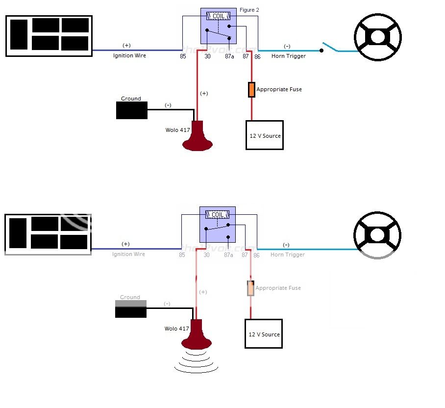
Is that pretty fair? These two images assume that the ignition is on. If it was off, the ignition wire would have a break in it.
Am I correct in that I would be piggybacking on both the ignition wire and the horn trigger wire? Basically, both of those wires would stay connected how they are from the factory, but in the middle, I'd run another piece of wire off of them to relay, correct?
Additionally, in this setup, wouldn't the factory horn stay active even when the ignition is on? I think I'm okay with that, just trying to make sure that I am visualizing this correctly. ------------- I'm a novice. Go easy on me.
Posted By: shortcircuit161
Date Posted: October 22, 2012 at 3:25 PM
You make a great point. Initially, it sounded good in my mind. I even drew it out but neglected to notice the factory horn would still be active with the ignition on.
Here is a revised formula (hehe). It involves 2 relays and cutting the blue factory horn trigger wire mentioned above.
Relay 1 -
Pin 85 - Ignition 12v
Pin 86 & Pin 30 - Switch side of factory blue horn wire
Pin 87a - Horn side of factory blue horn wire
Pin 87 - to Pin 86 of Relay 2
Relay 2 -
Pin 85 & Pin 30 - 12v Fused Constant
Pin 86 - from Relay 1 Pin 87
Pin 87 - positive wire from Wolo compressor
Pin 87a - No connection
Since the only thing that links Relay 1 and 2 is the single negative wire, you can probably connect Relay 1 under the dash and Relay 2 with the horn under the hood.
I believe this one will work a little better. When Ignition is On, the relay will be in "ready" mode. Once you press the horn switch, it will trigger both relays to remove the factory horn from the equation and trigger relay 2 for the Wolo horn.
When the ignition switch is off or during Accessory use, Relay 1 remains off even when pressing the horn switch. It will still allow you to use the factory horn thru Pin 87a.
Hope that makes sense.  -------------
Posted By: bvbull200
Date Posted: October 22, 2012 at 3:29 PM
Good. So I wasn't THAT crazy. I'll read this over a few times when I get some additional free time and possibly draw out a full schematic. Thanks for the response.
The ignition 12v is simply piggybacked off of the ignition wire, though, correct?
-------------
I'm a novice. Go easy on me.
Posted By: shortcircuit161
Date Posted: October 22, 2012 at 3:47 PM
That's correct. You would just piggyback off the ignition wire.
-------------
Posted By: bvbull200
Date Posted: October 22, 2012 at 11:41 PM
Alright, I think I have this thing laid out. If you could, look at these diagrams to see if I'm on the right path. They both assume that the horn is being pressed, since that is obviously what I'm concerned with. The first is when the ignition is off and the factory horn is activated (the gray horn). The second is when the ignition is on and the Wolo 417 is activated (thus deactivating the factory horn).
Ignition off, factory horn activated:
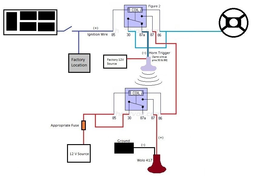
Ignition on, Wolo horn activated (factory horn deactivated):

The horn trigger wire will be easiest to access from right near the factory horn, so I will probably do that. The only wire that I really need to find is the ignition wire. Tough finding a solid diagram or layout of the actual locations of the wires. Your descriptions are certainly helpful, though, just need to locate the bundle of wires. ------------- I'm a novice. Go easy on me.
Posted By: shortcircuit161
Date Posted: October 23, 2012 at 6:17 AM
That looks perfect!! Much better setup than the original. 
Also, the ignition wire should be easy enough to find once you pull the lower panel off. It's the blue wire and will show 12v (or close to it) in the "On" and "Start" position.
Good Luck! Let me know how it turns out. -------------
Posted By: bvbull200
Date Posted: October 28, 2012 at 1:37 PM
To make getting my trigger wire to the engine bay easier, I thought of another possibility.
I have an empty fuse under the hood that would be for the sunroof (my car doesn't have one). I'm thinking I could just use an "add-a-circuit" and plug it in to that empty slot to trigger the relay.
Something like this:
https://www.parts-express.com/pe/showdetl.cfm?partnumber=071-585
That is already under the hood and a really short run to where I need to go anyways. I'm assuming that it only becomes energized when the car is either running or in the "acc" position. I've never used one of those before, though, so I'm worried that this is too easy to be valid. ------------- I'm a novice. Go easy on me.
Posted By: shortcircuit161
Date Posted: October 28, 2012 at 3:19 PM
That may work out really nice if you have access also to the factory horn wire under the hood. That should be a + trigger.
You would cut that wire and wire only one relay -
Pin 85 - to ACC circuit you found with the "add a circuit"
Pin 86 - Ground
Pin 30 - Switch side of the factory horn wire
Pin 87a - Horn side of the factory horn wire
Pin 87 - Positive terminal of the Wolo
The negative terminal of the Wolo would go straight to ground.
When the vehicle is off, you would use the factory horn and when ACC or IGN are on, the Wolo would take over. I don't like the idea too much of having the relay trigger on ACC since it will draw power from the battery if you are sitting for a while listening to music with the engine off. But it is definitely a better setup.
-------------
|