pulsed to steady output resistor
Printed From: the12volt.com
Forum Name: Relays
Forum Discription: Relay Diagrams, SPDT Relays, SPST Relays, DPDT Relays, Latching Relays, etc.
URL: https://www.the12volt.com/installbay/forum_posts.asp?tid=132724
Printed Date: March 20, 2026 at 1:48 AM
Topic: pulsed to steady output resistor
Posted By: turboled
Subject: pulsed to steady output resistor
Date Posted: November 20, 2012 at 6:27 AM
I have a question about this diagram:
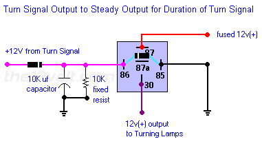
Why is the resistor there? As I see it, it is in parallel with the relay coil and capacitor. When the capacitor discharges, current needs to go to the coil and to the resistor at the same time, requiring a bigger capacitor for the same time delay. Also, the resistor adds non-necessary load and heat to the system.
I'd like to know if it's safe to remove the resistor, the capacitor value should be chosen according to the delay needed and the coil resistance.
Otherwise, this is a simple and useful solution.
Replies:
Posted By: howie ll
Date Posted: November 20, 2012 at 11:01 AM
Bloody good question. Mr.Idiot or Oldspark etc. like to comment?
-------------
Amateurs assume, don't test and have problems; pros test first. I am not a free install service.
Read the installation manual, do a search here or online for your vehicle wiring before posting.
Posted By: turboled
Date Posted: December 11, 2012 at 7:18 AM
That's all?
Posted By: oldspark
Date Posted: December 11, 2012 at 3:38 PM
From my first reply in component values in circuit shown here?:
oldspark wrote:
You needn't worry about the resistor - it is in parallel with the relay coil and has negligible effect. (If anyone disagrees, please chime in - eg, to dampen any oscillation?)
And that's not the first time I've proposed it is unnecessary.
PS - that 10k resistor has little impact on circuit values - it adds a mere 20mW and is probably well under 2% of the relay's loading.
And compared to the the inrush surge current of the cap, both resistor and coil currents are negligible.
Posted By: turboled
Date Posted: December 15, 2012 at 11:03 PM
I implemented the exact same circuit as above and tested 100% working with a 12 volts supply (the relay stays latched for 2 seconds), but when I install it in my car, the blinker stops working and clicks very fast. The relay doesn't even have time to energize and the blinker bulb doesn't flash. When I remove the circuit it works again. I only wired the coil part with blinker input and ground.
The car blinker is fully electronic so it seems to detect something wrong with this wired in, although it should see this circuit as low-wattage load connected in parallel with the 27w blinker bulb.
I tried both the front and rear blinker input with the same failure.
Posted By: turboled
Date Posted: December 15, 2012 at 11:08 PM
Could it be the cap taking too much current and the blinker momentarily thinking the bulb is shorted and halting the whole thing? If so I don't see what would be an easy solution...
Posted By: oldspark
Date Posted: December 16, 2012 at 1:33 AM
It could be. Adding a series resistor may help but it should probably be less than 1/4 the coil resistance at most.
Otherwise a buffer circuit is needed - ie, the diode & cap ( and discharge resistor) feed a MOSFET or transistor that energises the relay.
Posted By: turboled
Date Posted: December 16, 2012 at 8:59 AM
I read that instantly changing the voltage on a capacitor would require infinite current, that is probably what is making the blinker to go crazy. I will try adding a 10 or 20 ohms resistor in series with the diode, this should limit the current to the capacitor and hopefully it will charge rapidly enough within 0.25s. I don't know what should be the required wattage of the resistor because the initial current will be high but will decrease rapidly as the capacitor charges...
Posted By: oldspark
Date Posted: December 16, 2012 at 5:42 PM
Yes - it is infinite current but for an infinitesimal small time. Luckily we have annoying "non-ideal behavioral" things like resistance and inductance. But the theory is that initially the capacitor has no change and hence it acts like a short circuit.
The resistor "power" rating will handle that 1/∞ second short-circuit, but V^2/R = VxV/R can be used to calculate the (maximum) resistor power rating required. EG - using 15V [worst case for a 12V system; can use smaller (and allow for diode voltage drops etc) if it means a borderline situation] and assuming 22R resistance: 15x15/22 = 225/22 = 10.2W. Oops - that's unrealistically big (in practice) but I couldn't be bothered doing the proper integral calculation... (I think it is about 1W.)
Maybe try a 1/2W else a 1W (or 2W) resistor and see how that lasts.
Actually this example is why I don't like RC circuiting a relay direct. Instead I'd use a buffer - eg, an RC delay or hold-up that switches a transistor or similar which in turn energises (or de-energises) the relay. Hence much smaller components (eg, a 6V capacitor, and only uA to a few mA are involved - not the 80-250mA of a typical relay) and relay chatter is usually overcome. (Relay chatter or oscillation can occur - especially on discharge - due to the RLC (oscillator) nature of the circuit.)
Not that I even do that - I use a PIC because my "during flash cycle" circuits are for things like combined flasher/reversing lights (or flasher/stop lights etc) and I decided a PIC is simpler than using relays and other methods, plus it can also modulate (dim) the bulbs or LEDs if that's required.
If not for the convenience of a PIC (PIC 08's merely being a $few) I'd probably consider using a 555 timer which can power up to 200mA direct - eg, a relay coil - witha snubber (spike protection) diode across the relay coil of course!.
Posted By: turboled
Date Posted: December 16, 2012 at 9:21 PM
Ok, I added a 15 ohms/25W ceramic resistor in series after the diode. My blinkers now works perfectly. I agree with you oldspark that the circuit is on the heavy-duty side for what it does, it takes a lot of space in my driver's compartment. The circuit is cheap but big. The car's wires are so thin compared to those of the bosch relay I'm using, connecting them was a pain.
|