I am trying to connect a Raspberry PI to a relay to control a 12V output.
I have a OMRON G5LA-1 relay.
This is a 5 pin relay. each corner has a pin and one end has a pin in the middle.
The vendor diagram shows them PINS 1-5.
The output driver needs to supply 12V constant output and have a short ground pulse returning back to 12V constant.
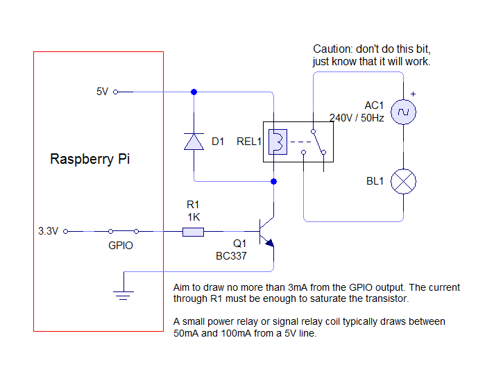
I found this diagram for a pulse output: 
Can someone let me know what pins to connect to what?
This is the instructions from the Raspberry PI site that shows good informatin - except what pins to connec to what from the relay:
https://www.susa.net/wordpress/2012/06/raspberry-pi-relay-using-gpio/
Here is a link to the OMRON Relay spec sheet : https://components.omron.com/components/web/PDFLIB.nsf/0/4F7D9D9CA026C97E862573930070AC4F/$file/G5LA_E_0911.pdf
The way they have them numbered, looks like pins 2 and 5 are the relays coil.
Relay Pin 2 to Raspberry +5V
Relay Pin 5 to Q1 collector
Relay Pin 3 to AC1
Relay Pin 1 to Motor
Relay Pin 4 not used - insulate
-------------
Soldering is fun!
Thank you very much.
I have drawn up what I think is the right way to merge the two diagrams (inputs and outputs) -- to have the output drive a sustaining 12V until the relay is pulsed, then it will drive GND and revert back to the 12V.
The Raspberry PI is trying to control a driveway gate motor for remote control to activate the gate to open or close. The INPUT line on the Gate Sensor will activate the motor when it detects a GROUND pulse input.

Is this right?
Thank you
Your last diagram is correct.
That Omron unit is the standard SPCO format for PCB relays.
-------------
Amateurs assume, don't test and have problems; pros test first. I am not a free install service.
Read the installation manual, do a search here or online for your vehicle wiring before posting.