timed 12v relay for power folding steps
Printed From: the12volt.com
Forum Name: Relays
Forum Discription: Relay Diagrams, SPDT Relays, SPST Relays, DPDT Relays, Latching Relays, etc.
URL: https://www.the12volt.com/installbay/forum_posts.asp?tid=132875
Printed Date: April 05, 2026 at 4:52 AM
Topic: timed 12v relay for power folding steps
Posted By: lvintegra
Subject: timed 12v relay for power folding steps
Date Posted: December 03, 2012 at 6:01 PM
So I want to start with I have little to no experience with relays and making them work for the functions I need them to do oustide just replacing / installing them after somebody else already did all the programming work. I am looking to do a retro fit on some power running boards on my Escalade that did not come with them from the factory. Because mine did not come with them from the factory I have to figure out how to control them myself, rather than the on board computer. One good thing is I know the color wiring diagram for the motors and it's function, as well as the door open / close trigger wires inside the factory harness. So here is my issue, I need to find a relay that can perform the following function:
Must have constant 12V power; once the door open trigger sends the signal to the relay I need the relay to allow 12v power to flow to the motor extension wire for 3 seconds and then stop. *the motors don't have stops therefore if a constant power was applied the motor would continually run even though the step would be fully deployed and eventually burn up*. Inversely, once the door close trigger sends the signal to the relay I need the relay to allow 12v power to flow to the motor retraction wire for 3 seconds and the stop. I have also been advised I should "diode" the relays so the 12v constant doesn't send feedback through the "door open / close trigger wires", not sure what this means exactly.
I put together the following diagram sketch of how I think it could possibly work
[IMG]https://img.photobucket.com/albums/v359/baggedLVintegra/RetrofitPowerRunningBoardSchematic.png[/IMG]
Does anybody have any experience with this type of application and/or timed relay experience and could point me in the right direction of where I could purchase a relay to perform these functions?
Any help is GREATLY appreciated. Thanks - Josh
Replies:
Posted By: lvintegra
Date Posted: December 03, 2012 at 6:04 PM
sorry the image embeddment didn't work, here it is 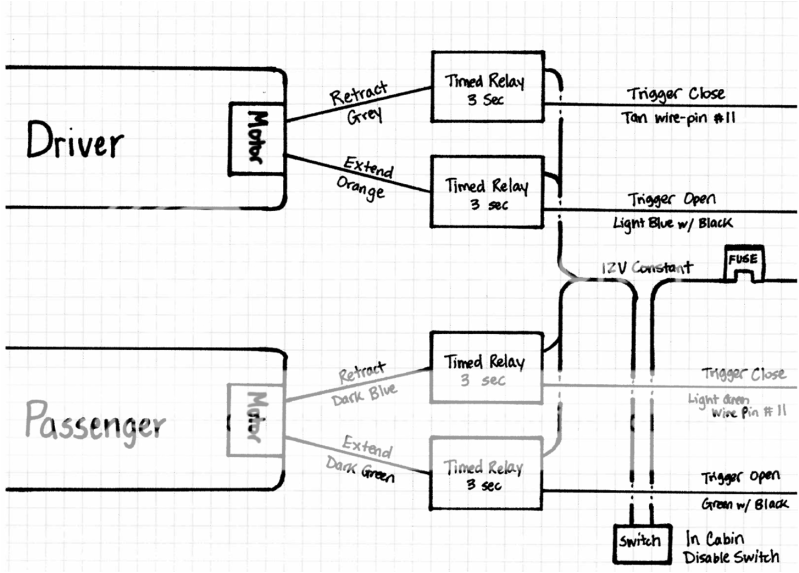
Posted By: kreg357
Date Posted: December 03, 2012 at 7:37 PM
Interesting project. It looks very do-able. The 3 second driver relay output is the challange.
While it might be possible with some sort of R/C control circuit to give the 3 second timing
another more logical and direct method to accomplish this would be with four 30/40 Amp
relays and 4 PAC TR-7 modules. Each TR-7 would monitor one door trigger and control one
relay. The relay wiring would be very simple and you could make up a small enclosure box
for each folding step, one for the right and one for the left. Here is a link to the PAC-TR7
module. https://www.the12volt.com/installbay/file.asp?ID=1031
Relay wiring - Pass side:
Relay 1 = Retract
Pin 85 to TR-7 #1 (-) White Output set @ 3 seconds
Pin 86 and 87 to +12V constant fused @ Step motor needs
Pin 30 to Step Motor Dark Blue
Pin 87A not used - insulate
Relay 2 = Extend
Pin 85 to TR-7 #2 (-) Output Output set @ 3 seconds
Pin 86 and 87 to +12V constant fused @ Step motor needs
Pin 30 to Step Motor Dark Green
Pin 87A not used - insulate
Both TR-7's would be programmed as Feature #15, one input pulse gives a 3 second output pulse.
TR-7 #1 Retract
Black to Chassis Ground
Red to +12V thru ON/OFF control switch
Brown to (-) Light Green door close trigger
White to Relay 1 Pin 85
TR-7 #2 Extend
Black to Chassis Ground
Red to +12V thru ON/OFF control switch
Brown to (-) GREEN/ Black door open trigger
White to Relay 2 Pin 85
I imagine there are less expensive ways to do this, so hopefully someone else can jump in with
another idea. ------------- Soldering is fun!
Posted By: lvintegra
Date Posted: December 03, 2012 at 7:43 PM
So the scenario you lay out above is just for the passenger side only right? So it would need to be doubled and would require (4) total relays and (4) total PAC TR-7s?
Posted By: lvintegra
Date Posted: December 03, 2012 at 7:44 PM
Sorry just re-read the post and it answered my question, made more sense the third time through :)....so yeah that's a bit pricey, which I don't mind if that is what HAS TO HAPPEN to make it work, but will entertain any ideas
Posted By: kreg357
Date Posted: December 03, 2012 at 7:47 PM
Yes, that is correct. One set-up like that for each sides' folding step. Total cost about $85 with fuses, etc but you can control the relays output to the second.
-------------
Soldering is fun!
Posted By: lvintegra
Date Posted: December 03, 2012 at 7:54 PM
So I'm pretty sure I comprehend your whole scenario and it seems that it would function exactly how I intend, however I am confused by the trigger input / output of the TR-7 being a negative? Wouldn't the door open trigger signal from the vehicle be outputing as a positive? Or am I confused? I have not actually tested to know, but you are much more experienced than I and may possibly already know
Posted By: kreg357
Date Posted: December 03, 2012 at 8:09 PM
Good point. You didn't mention the Escalade's year and I just assumed (-), but that is the
beauty of the PAC TR-7. If you find that it is a (+) trigger you can use the TR-7's Green (+)
Input trigger wire instead of the Brown wire listed above.
-------------
Soldering is fun!
Posted By: lvintegra
Date Posted: December 03, 2012 at 8:15 PM
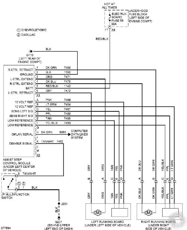
Ok I assumed that was a no biggie, but just trying to grasp everything....I greatly appreciate the help. The Escalade is an 07 BTW, attached is the factory power running board wiring schematic and then also aftermarket AMP power step wiring diagram that shows the trigger wires to tap into for the desired functions.
link to amp power steps installation instructions https://www.amp-research.com/wp-content/uploads/2010/05/download_btn.jpg
Posted By: lvintegra
Date Posted: December 03, 2012 at 8:17 PM
they need an edit post button lol it won't let me add the pdf but if you go to 07+ Escalade download on this page you can see it https://www.amp-research.com/products/truckaccessories/powerstep/
Posted By: kreg357
Date Posted: December 03, 2012 at 9:25 PM
The plot thickens...
Don't think you could just apply +12V to the extend wire to extend the step. It
would blow a fuse. Test the two motor wires to see if they rest at ground. If they do
you would have to connect the relays in to the circuit in the 5 wire mode. As follows :
Relay Pin 85 to TR-7 3 second output
Relay Pin 86 and 87 to +12V constant fused accordingly
Relay Pin 87A to controller side of cut Extend wire
Relay Pin 30 to motor side of cut Extend wire
Each relay would be similar.
As for the door triggers, most vehicles only have a trigger wire that is a simple pin switch.
When the door is open, it provides a ground signal (-). When the door is closed it provides
no signal ( an open ). I don't have the wiring for a 2007 Escalade to be able to see if your
information is correct with different wires supplying both a door open signal and another wire
supplying a door closed signal and their actual, respective, polarity. Something else to test
and verify. ------------- Soldering is fun!
Posted By: lvintegra
Date Posted: December 03, 2012 at 9:55 PM
So I should have explained this earlier, the controller will not exist on my setup. That wiring diagram is how it works from the factory, since mine didn't come with the power option all I have is the running boards, mounts and motors. The motors do have those 5 wires coming off it as indicated in the diagram, but the controller is what I am trying to create with the relays etc.
Posted By: kreg357
Date Posted: December 04, 2012 at 6:29 AM
Ok, so all you have is the folding step assy mounted to each side of the vehicle with the 5 wires in
a harness sticking out of each one ( not connected to anything )?
Additionally, as a test, on the left side you connected +12V to the Orange motor wire and ground to
the Gray motor wire ( for 3 seconds ) and got the step to extend. Then, you reversed the battery
leads ( +12V to Gray and ground to Ornage ) and got the step to retract.
Is all the above correct? ------------- Soldering is fun!
Posted By: lvintegra
Date Posted: December 04, 2012 at 9:07 AM
kreg357 wrote:
Ok, so all you have is the folding step assy mounted to each side of the vehicle with the 5 wires in
a harness sticking out of each one ( not connected to anything )?
Additionally, as a test, on the left side you connected +12V to the Orange motor wire and ground to
the Gray motor wire ( for 3 seconds ) and got the step to extend. Then, you reversed the battery
leads ( +12V to Gray and ground to Ornage ) and got the step to retract.
Is all the above correct?
Yes, all I have is the folding step assy mounted to each side of the vehicle with the 5 wires in a harness sticking out of each one (not connected to anything)
I actually do not physically have this in my possession (is in shipping to me) so I have not been able to test orange / grey wire you suggest above. I am going off what information I could get off other members attempting to make this work and knowledge I have from reading on the subject.
I know testing the scenario you lay it will determine how to ultimately make it work and sorry for not being able to provide this information just yet. Once I receive them, I will run the scenario you lay out above and will also test the door triggers for open / close to see if they are indeed postitive or a negative open close door pin as you mentioned previously
Posted By: lvintegra
Date Posted: December 04, 2012 at 9:18 AM
Also I believe in the diagram (for the left side) only the Grey and Orange wires control the extend / retract functions. I believe, but cannot 100% confirm, that the other 3 wires (tan yellow pink) run to a safety sensor that is setup to identify if the steps hit something to automatically shut down, which is a function I do not care to have with doing the retrofit. The diagram identifies the motor as M circled, and I believe the motor ground is simply it being bolted to the frame and the 2 wires control the function independently, but I will know more when I can actually physically test that theory
Posted By: howie ll
Date Posted: December 04, 2012 at 10:59 AM
Motor ground won't be the bolt to the frame for technical as well as obvious, i.e. bolt loosens.
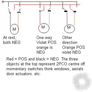
No, you will have two motor wires they sit on ground at rest then follow what Kregg told you. Look at this diagram:- motor_wiring.bmp
This applies to every motor in a car except the starter and AC compressor which have one live and ground through the bodywork.
But then they are only going in one direction. ------------- Amateurs assume, don't test and have problems; pros test first. I am not a free install service.
Read the installation manual, do a search here or online for your vehicle wiring before posting.
Posted By: lvintegra
Date Posted: December 04, 2012 at 11:17 AM
So I agree with your position on the motor wiring, would have a pos/neg for one function then switch neg/pos per say and the motor reverses.
After doing some more reading on the AMP steps (which operate like factory) the door triggers are most definitely negative ground door pin setups as Kreg mentioned earlier.
Posted By: lvintegra
Date Posted: December 04, 2012 at 11:19 AM
kreg357 wrote:
Ok, so all you have is the folding step assy mounted to each side of the vehicle with the 5 wires in
a harness sticking out of each one ( not connected to anything )?
Additionally, as a test, on the left side you connected +12V to the Orange motor wire and ground to
the Gray motor wire ( for 3 seconds ) and got the step to extend. Then, you reversed the battery
leads ( +12V to Gray and ground to Ornage ) and got the step to retract.
Is all the above correct?
So to correct the prior 3 posts, YES KREG ALL THE ABOVE IS CORRECT.....sorry guys, learning as I go. This is VERY informative and I think I'm starting to catch on
Posted By: KPierson
Date Posted: December 04, 2012 at 12:30 PM
What are you planning on using for the "trigger open" and "trigger close"? I read you mention the door pin, but most vehicles only have one door pin.
-------------
Kevin Pierson
Posted By: howie ll
Date Posted: December 04, 2012 at 12:35 PM
Easy Kevin gets some Ford NC switches and spends six months trying to mount them inside the doors.
-------------
Amateurs assume, don't test and have problems; pros test first. I am not a free install service.
Read the installation manual, do a search here or online for your vehicle wiring before posting.
Posted By: lvintegra
Date Posted: December 04, 2012 at 12:51 PM
KPierson wrote:
What are you planning on using for the "trigger open" and "trigger close"? I read you mention the door pin, but most vehicles only have one door pin.
According to the aftermarket AMP step instructions,
"Locate wire loom in door sill. Carefully remove wire wrap and find the trigger wire.
Drivers side: LIGHT BLUE wire with BLACK STRIPE
Passenger side: GREEN wire with BLACK STRIPE.
Locate the brown plug and using supplied Posi-Tap connector, splice into trigger wire.
2007-2008 Vehicles:
Drivers side: TAN wire- pin #11 Passengers side: LIGHT GREEN wire-pin#11"
So it suggest taping 2 wires per side, which would trigger Driver Open / Driver Close ; Pass Open / Pass Close....and the AMP steps work like Factory Equipped in that either door open on each side opens that side step.
Posted By: lvintegra
Date Posted: December 04, 2012 at 12:58 PM
Just found this by doing a forum search for 07 Escalade wiring
| Door Trigger |
see notes |
- |
see notes |
Notes: The LF door is gray/black at the DDM, brown 16 pin plug, pin 13. The RF door is BLACK/ white at the PDM, brown 16 pin plug, pin 13. The LR door is lt. blue/black at the BCM, pink plug, pin 15. The RR door is lt. GREEN/ black at the BCM, pink plug, pin 14. Use all four wires and diode isolate each.
The DDM (Driver Door Module) is in the driver door.
The PDM (Passenger Door Module) is in the passenger door.
The BCM (Body Control Module) is to the left of the steering column. |
Posted By: lvintegra
Date Posted: December 04, 2012 at 1:22 PM
The more I research and the more I read I reveal more....it appears to me that in the AMP instructions, and another brand Bestop, both say to tap the same 4 wires. I believe these 4 are Front Dr Trigger, Rear Dr Trigger, Front Pass Trigger, Rear Pass Trigger.
After reading this statement from Bestop
To test if the black controller (460.91), wire harness, motor and lights work, hook up to battery and touch any of the 4 door trigger wires to ground. The board for that side should go down and the lights should turn on. The board should go up and the lights should turn off when the wire is removed from ground. Note that a 2-second delay before the PowerStep returns to the stowed/retracted position.
I believe the controllers don't have a "door close trigger" rather once it loses the "door open trigger" it automatically reverses polarity 2 seconds later and retracts the step
Posted By: KPierson
Date Posted: December 04, 2012 at 2:02 PM
OK, that makes much more sense now. So the step is long enough for back passengers to climb in and out?
What do other people with these steps do for a controller?
-------------
Kevin Pierson
Posted By: lvintegra
Date Posted: December 04, 2012 at 2:10 PM
KPierson wrote:
OK, that makes much more sense now. So the step is long enough for back passengers to climb in and out?
What do other people with these steps do for a controller?
Yes the steps are long enough for back passengers as well.
Others either have the powered boards from the factory (BCM / Computer Controlled) or they have fixed running boards. To date,with all my research on numerous forums, nobody has successfully retrofit these before, so this is the first.
I have determined that for sure without a doubt these can be installed to work just like factory functionality, it's just a matter of two options:
1) "Design" a Controller module using timed relays and PAC TR-7 modules, plotting a wiring scheme, soldering diodes, running all the wires and testing it. Should work but not 100% confirmed without doing it all. Estimated cost $110 for all parts, LABOR intensive
2) Buy the AMP Power Step Control Module and Wiring Harness - Estimated cost $200, cleaner install NO design work
So the catch, the only issue with #2 is after talking to AMP Tech Support their module is programmed to run the motor for 5 seconds (the time it takes to extend / retract the AMP steps) but from my calculations it only takes 2-3 seconds tops for the OEM steps to reach full extend / full retract. Meaning the motors would run for 2 full seconds after the arms were maxed out. I'm concerned this 2 seconds of continued power to the motors will wear the motors out much sooner than they should.
Posted By: lvintegra
Date Posted: December 04, 2012 at 2:18 PM
so after comparing these two videos on youtube, there is no way the AMP steps are 5 seconds, they appear faster than OEM
[url]https://www.youtube.com/watch?v=tAHPMU0naig[/url]
this video at 1:17
[url]https://www.youtube.com/watch?v=PM7MvTKtRkg[/url]
Posted By: KPierson
Date Posted: December 04, 2012 at 3:34 PM
They probably run the motors a hair on the longer side as opposed to the shorter side. As the motors age they'll slow down. Running them for an extra 2 seconds forward and backwards most likely won't shorten the life too much and that way they won't have to worry about issues with the steps not fully extending five years down the road.
-------------
Kevin Pierson
Posted By: KPierson
Date Posted: December 04, 2012 at 9:49 PM
In reality, a microcontroller based design would be the most elegant approach. You could have two (-) inputs (one for front door, one for back), two outputs to drive relays, and a potentiometer that adjusts the outputs from 0-10 seconds.
If you are interested, I could put something together as long as you agree to cover my actual out of pocket hardware costs (I'll do the programming for free). I would guess the cost would be under $50 with relays and relay harnesses but if you are seriously interested I can work up an exact number. I would build you two separate modules - one per side. Each would have their own enclosure and Molex wire harness and two relays. The relays would be standard Bosch style relays in stackable harnesses.
Let me know if you are interested - I will build and test both modules and provide pictures before taking any payment from you. If for some reason they don't work I'll even take them back and refund your money - I'm just trying to help you out and keep myself busy!
-------------
Kevin Pierson
Posted By: lvintegra
Date Posted: December 05, 2012 at 8:25 AM
PM sent....sounds like a plan, I think we can make this work.
Posted By: KPierson
Date Posted: December 05, 2012 at 10:27 PM
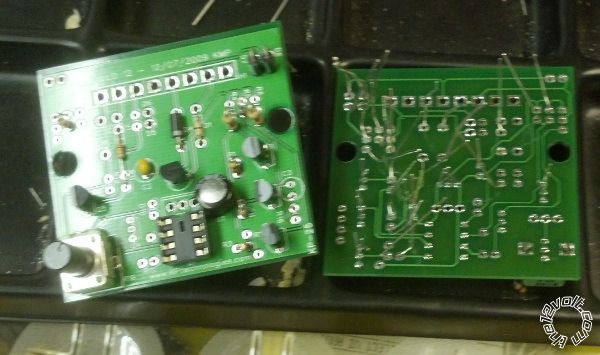
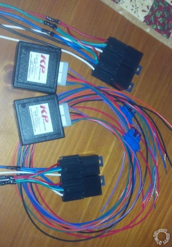
I messed around with this today. I wrote the code this morning and after I got the kids to bed tonight I put the hardware together. Not bad progress for 24 hours. My initial testing shows that it works perfect. The output is adjustable from 0-~10 seconds through the potentiometer. Pretty straightforward project!
 ------------- Kevin Pierson
Posted By: oldspark
Date Posted: December 05, 2012 at 10:47 PM
Blessed be those PICs!
And the pics showing a quality PCB and layout.
I was going to suggest a PIC - maybe even with current sensing (as I intend to do for my newly installed electric windows; mainly for a soft-start circuit for easy precise positioning, but also auto-closing and opening etc).
IMO the PIC is usually the simplest and cheapest solution for these somewhat complex applications, but to have a resource like KP to program or supply the circuit is the real clincher. (My year-old SMD PIC-08Ms are still merely soldered to an old 1988 SMD PCB.)
Yet again, my compliments KP!

Posted By: KPierson
Date Posted: December 05, 2012 at 11:13 PM
Not a PIC, an AVR! Slight, subtle difference but worth pointing out! Thanks for the compliments. Having proven hardware laying around makes small projects like this much easier.
-------------
Kevin Pierson
Posted By: oldspark
Date Posted: December 05, 2012 at 11:37 PM
Ah - the stamp or similar...
IMO far superior to a PIC, but that's my micro-processing experience that'd make it more versatile & easier.
But it's that painful learning curve and hardware hassle that you save people. I hope they realise and appreciate it!
I still look forward to my stamp-sized pre-populated $10 PIC PCB with MOSFET etc as my standard hardware for almost any simple implementation - eg, window controls; situational combinational headlight or lamp switching {stop, flasher, reverse, tail, bulb or LEDs); PWM & dimming; alarms and fan controls (off existing sensors), etc etc. But yeah, I have this minor problem with time -cum- priority [Read: I never seem to get that round-tuit!].
I envy your investment, and thank you for helping so many with your AVR & PIC etc solutions.
Posted By: howie ll
Date Posted: December 06, 2012 at 1:39 AM
Good lord Kevin, Hannah's board work is wonderful.
BTW My fiend is back in Florida end Jan/Feb/March.
-------------
Amateurs assume, don't test and have problems; pros test first. I am not a free install service.
Read the installation manual, do a search here or online for your vehicle wiring before posting.
Posted By: kreg357
Date Posted: December 06, 2012 at 3:48 AM
Excellent work and a very elegant solution! Add my compliments, too! 
The OP will be very satisfied with the results of KP's hard work. ------------- Soldering is fun!
Posted By: KPierson
Date Posted: December 06, 2012 at 6:10 AM
howie ll wrote:
Good lord Kevin, Hannah's board work is wonderful.
BTW My fiend is back in Florida end Jan/Feb/March.
Have your received the package I sent him last time he was here? I completely forgot about that already! ------------- Kevin Pierson
Posted By: howie ll
Date Posted: December 06, 2012 at 6:28 AM
Never got it, probably sitting in his letterbox!
-------------
Amateurs assume, don't test and have problems; pros test first. I am not a free install service.
Read the installation manual, do a search here or online for your vehicle wiring before posting.
Posted By: KPierson
Date Posted: December 06, 2012 at 7:06 AM
Doh! I sent it out the day we last spoke about it. Hopefully he finds it when he returns. If he doesn't let me know, I'll send another.
-------------
Kevin Pierson
Posted By: lvintegra
Date Posted: December 06, 2012 at 7:18 AM
I hate to state that I am so ignorant with regards to micro electronics that all I see is a board in the pictures, but everything seems nice, neat and clean, just wish I understood this enough to really appreciate the complexity. Having said that, I am VERY appreciative of the work Kevin is doing and its things like this that make these forums worth it and Kevin's willingness to assist shows his and his companys passion for customer service and satisfaction. Its these things that give me hope and pride for businesses in this era and wish more companies were as stand up as Kevin.
Posted By: KPierson
Date Posted: December 06, 2012 at 7:30 AM
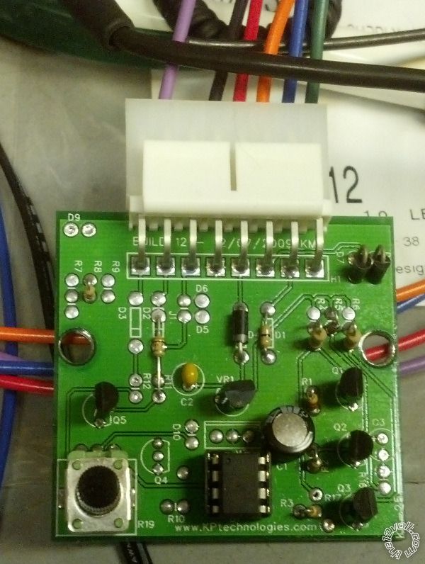
It's actually a pretty basic board. The "center" is the IC chip - it is an 8 bit microcontroller running at 1.2mhz. Everything North of the microcontroller is related to the 5vdc power supply. These boards use LDO regulators which minimize idle current (each board draws only 2.5mA at idle). The power supply includes a diode for reverse polarity protection.
To the right of the IC chip are three separate circuits - two outputs (Q1 and Q3) and one high impedance input (Q2). All three circuits have dedicated drive transistors and necessary base and collector resistors to prevent damage to the transistors from over current situations. In the top right of the board are two diodes, these are to protect the output transistors from back current created by driving inductive loads (and very relevant to another thread on this site)
To the left of the IC chip is the adjustable potentiometer that goes to a 10 bit (1023 steps) Analog to Digital converter inside the IC. However, in this application, I am only using 8 bits (255 steps). Because this is an 8 bit controller and because timing resolution is not a high priority, I chose to stick with 8 bits on the converter. Otherwise, I would have had to done 16 bit math which is a bit more complicated and can't be justified by this project. Also to the left is the second input circuit for the other door pin. Like the other input, it has its own transistor and resistors.
Like I said, the hardware is fairly basic, it's the software that makes the module work!
-------------
Kevin Pierson
Posted By: howie ll
Date Posted: December 06, 2012 at 9:08 AM
Kevin, don't worry he lives in a secure area, the only neighbourhood problem being Tiger Woods driving into the gateposts!
He'll be back first week in March, we can take it from there.
did you send it by US mail, if so it should be OK.
Sorry about the references to Hannah, I always remember her name because it's the same as my Mum and Granddaughter's.
-------------
Amateurs assume, don't test and have problems; pros test first. I am not a free install service.
Read the installation manual, do a search here or online for your vehicle wiring before posting.
Posted By: howie ll
Date Posted: December 06, 2012 at 9:10 AM
I just realised what I said, Tiger Woods driving into the gateposts.  ------------- Amateurs assume, don't test and have problems; pros test first. I am not a free install service.
Read the installation manual, do a search here or online for your vehicle wiring before posting.
Posted By: KPierson
Date Posted: December 06, 2012 at 10:06 AM
No worries Howie! She actually wanted to help with these last night, I started assembling them while she was eating her bed time snack. She wanted me to save one for her to do!
-------------
Kevin Pierson
Posted By: lvintegra
Date Posted: December 06, 2012 at 10:35 AM
Hey Kevin quick question, what gauge wiring is used for all the connectors? I was thinking of plumbing all the wiring this weekend so I could have it all ready in waiting once the modules come to just hook up and go.
Posted By: KPierson
Date Posted: December 06, 2012 at 10:39 AM
The wiring on the module itself is all 20awg. The power wire is inline fused at 3A. The relay contact wiring has thicker 14 awg wire.
-------------
Kevin Pierson
Posted By: lvintegra
Date Posted: December 06, 2012 at 10:39 AM
Was going to go pick up some wire, in-line fuse, some Posi-Taps and heat shrink butt connectors...unless maybe you had those readily available and could send with the modules
Posted By: howie ll
Date Posted: December 06, 2012 at 11:04 AM
No. You're going to pick up some wire SOLDER and HEAT SHRINK.
Never ever use T-Taps, it won't last 5 minutes.
As for you Kevin, train em young!
-------------
Amateurs assume, don't test and have problems; pros test first. I am not a free install service.
Read the installation manual, do a search here or online for your vehicle wiring before posting.
Posted By: lvintegra
Date Posted: December 06, 2012 at 11:12 AM
So I generally always solder, but in the confined space where the motors will be mounted once installed it wouldn't be feasible to solder the wires if I pre-ran them.
Now if I wait and pre-wire the modules before install then I could solder. Thats the dilemna
Posted By: howie ll
Date Posted: December 06, 2012 at 12:14 PM
Wait and solder that way it will last longer than a week.
-------------
Amateurs assume, don't test and have problems; pros test first. I am not a free install service.
Read the installation manual, do a search here or online for your vehicle wiring before posting.
Posted By: kreg357
Date Posted: December 06, 2012 at 2:45 PM
Exposed T-Taps under the cab of a truck? No way! Wait and solder everything. Use heat shrink tube and then wire loom everything nice and neat.
-------------
Soldering is fun!
Posted By: lvintegra
Date Posted: December 06, 2012 at 3:24 PM
Yeah I'm just going to wait, have a full schedule this weekend anyway so I'll just postpone the wiring until I have everything ready. Planned to loom everything anyway but I agree solder is the way to go!
Posted By: lvintegra
Date Posted: December 06, 2012 at 4:12 PM
and actually the T-Taps are ONLY for the taps into the door wiring inside the door panel, nothing else
Posted By: howie ll
Date Posted: December 06, 2012 at 4:43 PM
Shoving them inside the door panel is almost as bad as the engine bay, vibration damp and corrosion without the heat, just wait for two weeks of door slamming.
DON'T EVER USE THEM.
-------------
Amateurs assume, don't test and have problems; pros test first. I am not a free install service.
Read the installation manual, do a search here or online for your vehicle wiring before posting.
Posted By: KPierson
Date Posted: December 07, 2012 at 8:41 PM
Finished this project up tonight! ------------- Kevin Pierson
Posted By: lvintegra
Date Posted: December 08, 2012 at 10:35 AM
Sweeeeet! Shoot me a PM with payment info and we can get it all taken care of. Thanks again!
Posted By: lvintegra
Date Posted: December 10, 2012 at 9:01 AM
So I have a concern, which is NOT verified yet, but I thought I'd gauge insight on a potential problem. I physically got the running boards / motors in my hands last night. I briefly tried to run 12v power and ground off the battery to the motor to test the reverse polarity theory and I got nothing. No combination of 2 wires gave power to the motor. I know 100% they work as the seller sent video of them in operation and I don't question his integrity one bit. Looking at the wiring diagram on Page 1 of this thread, it appears (for the drivers side) that:
There are 2 wires coming off the motor (Grey and Orange) and 3 wires "off to the side of the motor" (Tan Yellow Pink)
On the actual motors there is just a bundle of 5 wires coming out of the same location on the motor (Black Red Yellow Green and Orange)
My initial assumption, atleast beause of the diagram, was that the Grey / Orange wires controlled the motor and the Tan / Yellow / Pink were tied to a safety sensor for the steps. Now I'm starting to think that the factory step controller provided power to the motor whilst monitoring the "saftety sensor" and therefore straight power to the Grey / Orange would not trigger the motor.
Do you guys think I may have to jump the 3 wires intended for the safety sensor for it to realize it can operate? If so how should I go about accomplishing this? In the diagram these wires are labeled as "Low Reference" "Sens Left Sig" and "10 Volt Ref" respectively.
Posted By: KPierson
Date Posted: December 10, 2012 at 10:02 AM
I would try grounding the low reference and putting 10vdc on the 10 volt ref and see what happens. I would assume that the sensor is inside the steps and that the sensor is sending something back to the controller. I would guess that there is some sort of interlock in the steps that if the sensor becomes inoperable the steps won't move.
To get your 10 volts you can use a 7810 voltage regulator or a 7812 regulator feeding a voltage divider? 10 volts is a weird voltage to work with in a car. You may even try hooking a 9vdc battery up to it just for testing (make sure you connect the ground of the battery to the car or to your power supply so that both systems share a ground).
If you can get the steps to work you can start playing with the parameters that make it work - ie will it work on a 5vdc or does it have to be 10vdc? The closer you can get to 5 the better off you'll be.
-------------
Kevin Pierson
Posted By: lvintegra
Date Posted: December 10, 2012 at 10:52 AM
So:
-normal 12v and ground to the 2 "motor" wires
-ground the "low reference" wire
-apply 10v power to the "10 Volt Ref" via the 7810 voltage regulator
-but what about the last wire "Sens Sig Left"?
2 issues arise with this....1) the wiring diagram I have does not match the colors of the actual wires coming out of the motor, so I can't readily identify which ones do what. I have a feeling getting my hands on the right wiring schematic would be tough. 2) I've never used a "voltage regulator" nor do I know where to get one locally, would probably have to order online or something
Posted By: KPierson
Date Posted: December 10, 2012 at 11:35 AM
I would ignore the sensor wire at this point. I believe it is an output, not an input. Not having the correct wiring diagram may make it a bit more difficult to figure out which wire does what.
I have never used a 7810 either, I am only assuming they make them. You would have to order one, from some place like Mouser.com or Digikey.com. They are very simple devices, apply voltage in that is at least one volt higher then desired voltage out, ground the ground pin, and then use your voltage out pin as desired. They are 3 pin transistor type devices. Like I said, I would start with a 9vdc battery and see if it works with a 9vdc. A 7809 may be easier to find then a 7810. A 7805 (5vdc regulator) is in stock at RadioShack which is why I said the closer you can get to 5vdc and have the system working the better off you are.
-------------
Kevin Pierson
Posted By: lvintegra
Date Posted: December 10, 2012 at 11:53 AM
so miraculously I have a Cadillac techs number from another forum who we've bought and sold parts from and I texted him to see if he could help with the diagram and he has an Escalade on his lift right now with the factory installed power running boards and is going to map over the wires across the connector for me. Atleast I'll know each wires function now. The rest seems to be the more difficult part. Hopefully I can do the 9v battery trick tonight and give it a try
Posted By: lvintegra
Date Posted: December 10, 2012 at 1:15 PM
So I got my hands on the specific 07 power running boards wiring schematic, but it is extremely difficult to read (due to scan / fax) so I won't upload it. The routing of the wires is all similar to the other I posted but some have different titles:
Both sides "2 motor power wires" are the same, it's the 3 sensor wires that are different (this just talking driver side):
Original Schematic - Tan "Low Reference" ; 07 Specific Schematic - Tan "Running Board Motor Halt Sensor Left Return"
Original Schematic - Yellow "Sens Left Sig" ; 07 Specific Schematic - Yellow "Running Board Motor Halt Sensor Left Signal"
Original Schematic - Pink "10 Volt Ref" ; 07 Specific Schematic - Pink "Running Board Motor Halt Sensor Left Reference"
The 07 specific schematic does not call out any of the wires being 10v specifically, although I find it hard to believe in 07 they used the controller one way with a 12v reference to the signal and later changed it to a 10v reference for the signal.
Does any of this new information change your proposed plan? Would using 12v to the reverse wire instead of 10v do any damage?
Posted By: KPierson
Date Posted: December 10, 2012 at 3:58 PM
I would guess that there is an encoder in the motor that sends 10vdc pulses back to the controller. The controller then looks for the pulses to stop to know when the sill is completely in or out (ie motor stall condition). It's possible that the system would work at battery voltage, but I would start low and work your way high. Is there anything you can take apart on the motor to check out the wiring? There may something as simple as a relay interlocking the motor wiring to the sensor power wires.
-------------
Kevin Pierson
Posted By: lvintegra
Date Posted: December 10, 2012 at 4:25 PM
I've been thinking about that today (pulling the motor apart), I may just do that tonight if I get the time and its feasible.
Posted By: lvintegra
Date Posted: December 10, 2012 at 10:54 PM
so I took apart the motor and this is what I found inside
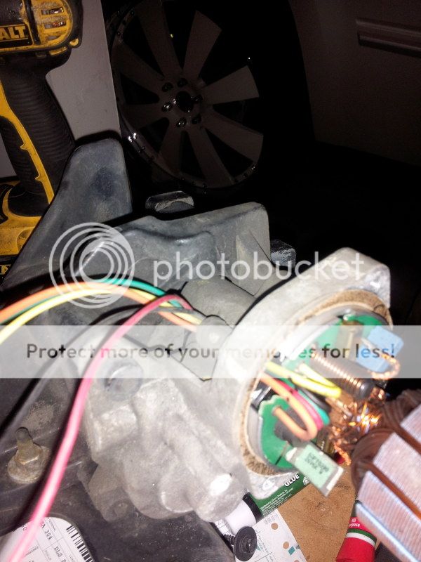
it doesn't appear to be any kind of relay that I can tell, the wires just go straight into the board.
I attempted to wire it up as you suggested earlier except for I didn't have a 9v battery so I just briefly touched the "10v ref" to the 12v battery post with a very very small wire and it began working as it should. The wire got pretty tacky to the post quick so I quickly pulled it off.
But now I know for sure what wires do what, how to bypass the safety sensor although I have to figure out how to make it constant. Do you suggest just running the ground of the "safety sensor" to the rest of the grounds permanently and branching off my already ran 12v power regulating it down directly to the "10v ref" permanently?
Posted By: KPierson
Date Posted: December 11, 2012 at 10:49 AM
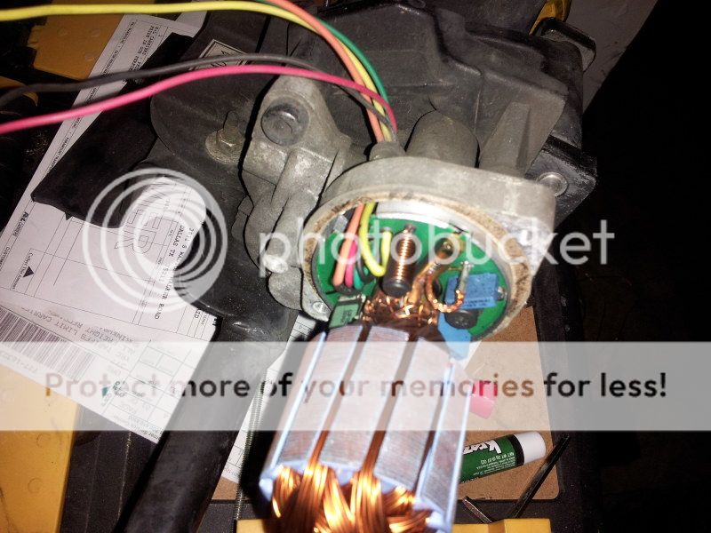
Do you have an ammeter? I would be interested to know how much current the 10v source draws.
Also, the little blue things look like they might be relays, any chance of getting better pictures or part numbers off of them?
I have an electronics warehouse near me, I'll see if I can find a 7810 or 7809 in stock locally.
-------------
Kevin Pierson
Posted By: lvintegra
Date Posted: December 11, 2012 at 10:53 AM
Don't have an ammeter unfortunately....I could probably take the motor case back off tonight and get better pics / P/Ns off those relays tonight. Anything other info you might possibly need while I'm in there?....also have the Modules shipped?
Posted By: lvintegra
Date Posted: December 11, 2012 at 5:52 PM
So I picked up a 9v battery on the way home and re-tested it as layed out previously and it still worked well.
I couldn't get a close enough picture of the "blue things" to read the print but it looked like this:
6103311829521
^ 1 "a backwards 4" K63U6
Posted By: lvintegra
Date Posted: December 14, 2012 at 11:10 AM
Hey Kevin your inbox is full so my last PM didn't go through......my plan was to branch off the 12v constant power off the battery that I already ran down by the step motors as the input to the regulator, ground the center pin and output to the motor sensor. It would be a constant regulated power. Is that a bad idea?
Posted By: KPierson
Date Posted: December 14, 2012 at 11:23 AM
Sorry about that, it is cleaned out now.
The effectiveness of that setup depends on how much current the sensor uses. If it pulls a couple mA it won't be a problem. If it is latching a relay at ~150mA it will drain your battery after a few days of sitting.
A more efficient way to run the sensor would be to power it right off the +12vdc output of each relay. You'll need to diode isolate each output to prevent backfeeding and fuse blowing. Wire two separate 1A diodes directly to each relay output (pin 30 on both relays) with the stripe closest to the regulator. Connect the striped sides of the diodes together and use that point as the feed for the regulator. This way, the regulator will only be on when the steps need to move.
-------------
Kevin Pierson
Posted By: lvintegra
Date Posted: December 14, 2012 at 1:16 PM
This confuses me with regards to the :+12vdc output of each relay. There are 2 wires that control the motor, it was my impression that 1 one would come out of 2 relays and hook to the 2 motor wires. In that case they would have to be able to reverse polarity to make the motor extened / retract and therefore neither would ever be constant output +12vdc. So how would I hook up the 12v power to the regulator if neither was constant power?
Posted By: KPierson
Date Posted: December 14, 2012 at 3:06 PM
Both motor wires (Pin 30 of two relays) will rest at ground going to the motor. When either relay is energized the ground will be disconnected and 12vdc will be connected to Pin 30, thus outputting 12vdc on the motor wire.
The diode that needs to be connected to each motor wire will only allow 12vdc to pass through it. So, what you'll end up with, after the two diodes are connected to each other, is a wire that will go to 12vdc whenever the system is trying to extend or retract the boards.
-------------
Kevin Pierson
|