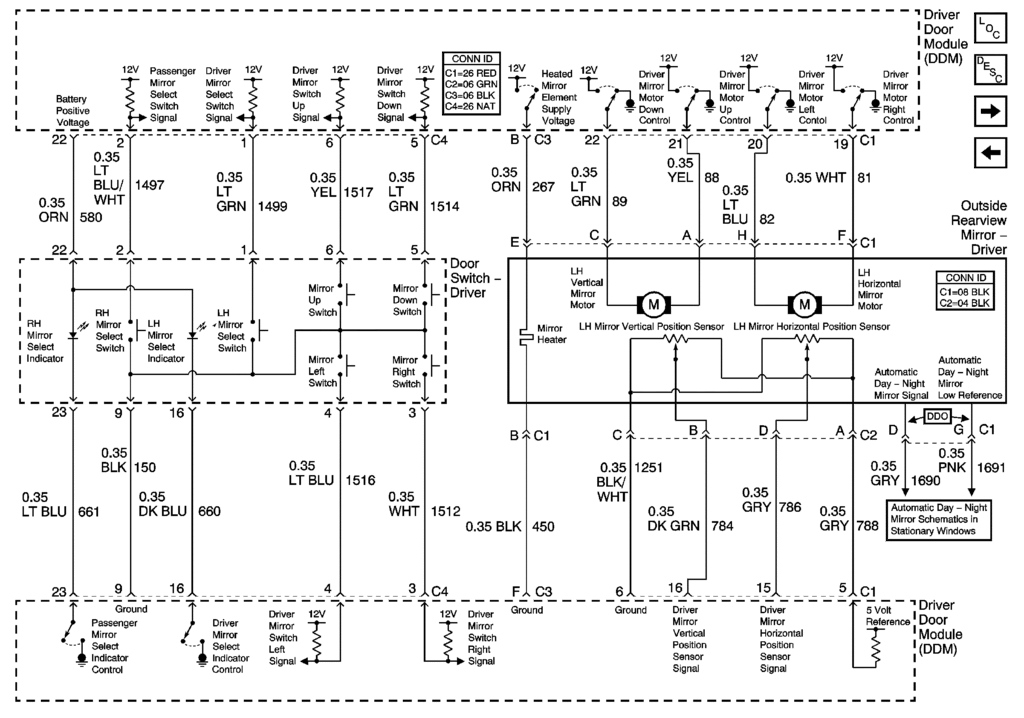
I have this schematic which I somewhat understand but I'm not certain how the relay/ AB switch would function. I can pretty much tell that Blue/Red Stripe is Hot and WHITE/ Black Stripe is Ground but the rest is beyond me.
There are 8 wires coming from each mirror
Any help would be greatly appreciated. There is an A/B switch in this switch.
Hopefully I gave enough info.
Thanks so much
Dave


-------------
Be part of the solution not part of the problem!!!
It looks like 3 wires from each mirror to me.
It should be a normal polarity reversal for each motor depending on the direction.
EG, for left & up, GND is connected to the motor common while the +12V goes to each motor thru the Left & Up switches respectively.
For right & down, +12V is switched to the motor common while GND goes to each motor thru the Right & Down switches respectively.
wascapsfan wrote:
I have this schematic which I somewhat understand but I'm not certain how the relay/ AB switch would function. I can pretty much tell that Blue/Red Stripe is Hot and WHITE/ Black Stripe is Ground but the rest is beyond me.
There are 8 wires coming from each mirror
Any help would be greatly appreciated. There is an A/B switch in this switch.
Hopefully I gave enough info.
Thanks so much
Dave


-------------
Be part of the solution not part of the problem!!!
The last shows the same polarity reversal to each motor but done with SPDT relays instead of a DPDT switch.
But those motors also have position sensing variable resistors. The DDM compares that to its setting and adjusts them to match.
What are you trying to do?


