turn signal to steady relay
Printed From: the12volt.com
Forum Name: Relays
Forum Discription: Relay Diagrams, SPDT Relays, SPST Relays, DPDT Relays, Latching Relays, etc.
URL: https://www.the12volt.com/installbay/forum_posts.asp?tid=133173
Printed Date: March 19, 2026 at 1:46 PM
Topic: turn signal to steady relay
Posted By: wpj74
Subject: turn signal to steady relay
Date Posted: January 03, 2013 at 4:45 PM
hey all you ahve been a great referance so far for my learning of circuits its getting me more adventouruse.
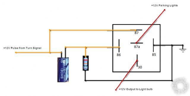
https://www.the12volt.com/relays/relaydiagram22.html
in the above referance diagram,
I wanted to know if I can connect the grounds form the cap and resister on the 86 terminal of the relay to the 85 terminal as they would be the same ground potential?
Help would be great I want to see if I can fit this all in the relay adapter
Thanks again
Will
Replies:
Posted By: turboled
Date Posted: January 03, 2013 at 6:49 PM
Yes of course, you can ground everything to pin 85, that's basically what I did (the cap goes between 85 and 86). You don't need the resistor. You can refer to recent topics on the same subject.
The cap can be seen as a short circuit by your car electronics. You may need to add a resistor in series before the cap if you car's blinker goes crazy.
Posted By: wpj74
Date Posted: January 03, 2013 at 7:48 PM
Ok great thanks
I was not sure why they were using the resistor anyways. Thoughts?
Posted By: oldspark
Date Posted: January 03, 2013 at 9:40 PM
That seems to be an oft recurring question of late, eg from my first reply to pulsed to steady output resistor:
oldspark wrote:
From my first reply in component values in circuit shown here?:
oldspark wrote:
You needn't worry about the resistor - it is in parallel with the relay coil and has negligible effect. (If anyone disagrees, please chime in - eg, to dampen any oscillation?)
And that's not the first time I've proposed it is unnecessary.
PS - that 10k resistor has little impact on circuit values - it adds a mere 20mW and is probably well under 2% of the relay's loading.
And compared to the the inrush surge current of the cap, both resistor and coil currents are negligible.
That pulsed to steady output resistor thread may be worth a read if you have problems (ie, capacitor inrush current too big).
Posted By: wpj74
Date Posted: January 04, 2013 at 4:50 PM
Thanks everyone.
I completed testing the circuit today and it works great.
I was getting a small spark when energizing the circuit so I added a small resistor one side of the cap and that took the spark away discussed in the other thread above.
about $22 for two circuits includes all parts. Much better than the 75 timer relay someone else suggested.
thanks
Will
Posted By: oldspark
Date Posted: January 04, 2013 at 6:22 PM
The timer relay may be more physically elegant, but I too would opt for the $53 cheaper (or 3 for 1) option.
And of course you now have a solution that you can fix using commonly available cheap parts rather than source a specialised part.
You've already done the hard work (circuit & wiring) so repairs should be easy.
Using other DIY circuits to avoid big caps and big current-limiting resistors may be even cheaper and more elegant, but that Pulsed to Steady Output brute force method works and it doesn't take years to build (LOL).
And isn't turboled's info and solution great?! (And all before his 10th post as a "Junior Member" LOL!)
[ Another strike for DIYers, the12volt, and its members.  ]
Posted By: korrupt3dazn
Date Posted: April 07, 2013 at 7:57 PM
oldspark wrote:
The timer relay may be more physically elegant, but I too would opt for the $53 cheaper (or 3 for 1) option.
And of course you now have a solution that you can fix using commonly available cheap parts rather than source a specialised part.
You've already done the hard work (circuit & wiring) so repairs should be easy.
Using other DIY circuits to avoid big caps and big current-limiting resistors may be even cheaper and more elegant, but that Pulsed to Steady Output brute force method works and it doesn't take years to build (LOL).
And isn't turboled's info and solution great?! (And all before his 10th post as a "Junior Member" LOL!)
[ Another strike for DIYers, the12volt, and its members. ]
Hi,
I have been trying to get this thing to work all weekend and can't seem to figure it out.
I drew up a diagram of how I thought this diagram would go...im pretty sure I wired it up wrong. I hooked up volt meter to pin 86 and see it jump from 11.5v and then drops to 0. Im pretty sure if I did it right that voltage would stay at 11.5v for the duration of the turn signal being on.
Posted By: wpj74
Date Posted: April 07, 2013 at 8:27 PM
Dude, I don't get what you are doing with this circuit why are you involving the parking,lights?
Posted By: korrupt3dazn
Date Posted: April 07, 2013 at 9:45 PM
Sorry I should be more clear on what Im trying to do. Im trying to wire up my trailer lights. The problem is the manual
says that the Parking Lights and Turn signal is on the same line. On my car I have a seperate bulb for turn signal and parking lights.
My goal is to power the trailers lights when parking light is on. Then have the relay switch over to the turn signal (87).
Since turn single is pulse I need to convert it to a steady output. Once its steady output the turn signal pulse can flow to pin 87.
Then when im done turning the relay sets it back to parking lights (87a). On a side not. I tried connectint the cap to 86 and 85 After reading post #2. after about 30 seconds it exploded. Not a plesant sound in a small room. Im seriously doing something wrong lol.
Posted By: wpj74
Date Posted: April 07, 2013 at 10:27 PM
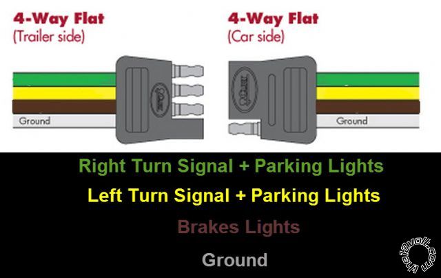
Hey mate, I gotta now, you are trying to make a cheap trailer light module.
I want you to check this closely.
white is ground
brown is running lights
yellow and green are turn plus break
this is typical trailer lights but you say the running/parking lights and the break lights are opposite in your diagram.
if in fact you have those wrong then here is a simple setup from my friend big blue bus.
https://sprinter-source.com/forum/showpost.php?p=214334&postcount=89
enjoy.
Posted By: wpj74
Date Posted: April 07, 2013 at 10:59 PM
Hey also your cap is connected wrong, it needs to be connected the same as the resistor.
treat it like a battery.
Posted By: oldspark
Date Posted: April 07, 2013 at 11:03 PM
FYI - the last diagram does not have diode, hence there is no delay or hold-up time (the cap discharges thru the other bulbs).
Posted By: korrupt3dazn
Date Posted: April 08, 2013 at 1:07 AM
wpj74] wrote:
Hey also your cap is connected wrong, it needs to be connected the same as the resistor.
treat it like a battery.
Probably explains why it exploded lol. Thankfully I was wearing safety glasses. Never know when stuff might come flying at you. 
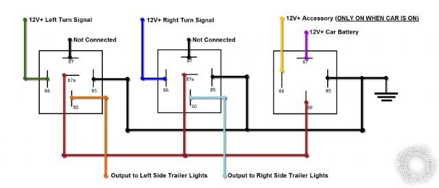
So after reviewing the link you gave me it kinda got me more confused on how he got it to work with no ground. So I drew up a new diagram. I tested it out and it works on my test bench. We will have to see once I wire it up to the car. Let me know what you guys think. As you can tell I'm a super rookie, but I feel good about this one.
Posted By: oldspark
Date Posted: April 08, 2013 at 2:09 AM
Geez - I missed that the cap was connected wrong! Not that it should have blown up, but the relay would not have turned on (well, not for long if it did...).
But if you are trying to combine flashers with other lights (whether park/clearance, stop or reverse), then that 3-relay circuit won't work.
Such circuits MUST have a time function unless relays are used to connect the flasher can... IE, replace the can before the left/right switch with a link and have the switch turn on separate L & R relays that disconnect the "other" light (brake, parker, reverse) and connect the can to the bulbs - that requires a DPDT relay (or SPDT + SPST) per side (eg, like advrider - Making rear turn signals double as additional brake lights).
But also have a look at the exledusa LED flasher devices tpc-v2 or tpc-v3 ($17 & $27 a pair respectively) - I reckon they can drive a relay if the lamp current is too high. I reckon that's the best and cheapest option (unless you make & program your own ~$10 PIC etc based circuit).
|