Wiring SPDT Relay with Two Sources
Printed From: the12volt.comForum Name: Relays
Forum Discription: Relay Diagrams, SPDT Relays, SPST Relays, DPDT Relays, Latching Relays, etc.
URL: https://www.the12volt.com/installbay/forum_posts.asp?tid=133209
Printed Date: March 19, 2026 at 6:55 PM
Topic: Wiring SPDT Relay with Two Sources
Posted By: arkansas_mystic
Subject: Wiring SPDT Relay with Two Sources
Date Posted: January 06, 2013 at 9:06 PM
Hello,
I'm looking for assistance wiring some auxiliary reverse lights on my vehicle. I have a SPDT relay that I'm using and would like to have two sources to trigger the relay. I would like the relay to activate and turn on the lights when either a) I put the vehicle into reverse or b) I flip a switch I've installed in the cab (SPST). This is the wiring diagram I tried using:

With this wiring configuration, the backup lights work when I put the vehicle in reverse but not when I flip the switch. If I disconnect the wire from the factory backup lights and connect the wire from the switch in it's place on post 85, the lights work with the switch.
Does anyone have any suggestions on making this work? I would greatly appreciate any input.
I'm looking for assistance wiring some auxiliary reverse lights on my vehicle. I have a SPDT relay that I'm using and would like to have two sources to trigger the relay. I would like the relay to activate and turn on the lights when either a) I put the vehicle into reverse or b) I flip a switch I've installed in the cab (SPST). This is the wiring diagram I tried using:
With this wiring configuration, the backup lights work when I put the vehicle in reverse but not when I flip the switch. If I disconnect the wire from the factory backup lights and connect the wire from the switch in it's place on post 85, the lights work with the switch.
Does anyone have any suggestions on making this work? I would greatly appreciate any input.
Replies:
Posted By: KPierson
Date Posted: January 06, 2013 at 10:14 PM
When the relay is not energized Pin 87A is connected to Pin 30. So, when you flip the switch on right now you are connected 12vdc from your battery, through the switch, back to 12vdc from the battery through the relay.
Unless your switch is rated with enough current to power your lights directly you shouldn't be powering the lights through the switch (after all, that is what the relay is for - high current switching).
Your best bet would be to go to RadioShack and get two 1A rectifier diodes (1n400x where x can be virtually any number). Connect the back up light through the first diode to the relay and then connect the output of your switch through the other diode to the same pin (pin 85) on the relay. Make sure on both diodes the silver band is closest to the relay. The diode will prevent one source from backfeeding in to the other source and will allow both sources to turn the relay on and off independently.
-------------
Kevin Pierson
Posted By: arkansas_mystic
Date Posted: January 06, 2013 at 10:21 PM
I'm new to all of this, but that was my understanding based on some research into how SPDT relays work. What I do not understand is why the wiring diagram from a light manufacturer (not the same manufacturer as the lights I installed) shows that it will work that way. I've also spoke to a guy on a vehicle specific forum I'm on and he has reverse lights wired as shown in that diagram and they work.
Regardless, I should be able to get the diodes as you suggested and get those installed. Just to be sure, you're saying connect the wire from the factory backup lights and the wire from the switch to post 85. The wire going to my auxiliary backup lights would remain connected to post 87. Is that correct? Thank you very much for your reply.
Regardless, I should be able to get the diodes as you suggested and get those installed. Just to be sure, you're saying connect the wire from the factory backup lights and the wire from the switch to post 85. The wire going to my auxiliary backup lights would remain connected to post 87. Is that correct? Thank you very much for your reply.
Posted By: oldspark
Date Posted: January 07, 2013 at 1:02 AM
It sounds like it is not an SPDT relay. It may be faulty, else a dual-output SPST type.
But to add to what KP said, IMO that's a stupid setup. Why should you need a heavy duty switch and its heavy wiring and a fuse when that already exists?
I'd recommend KP's method - a light duty fused switch and wiring with two diodes (one or both which may be optional depending on the switch power source) for a common connection at the relay coil (#86 with #85 to GND).
Posted By: turboled
Date Posted: January 07, 2013 at 6:20 AM
It looks like the mistake in the original diagram is that the latch circuit is reversed, pin 30 should be connected to the backup light output, 87 to the power source, 87a to the switch.
Posted By: turboled
Date Posted: January 07, 2013 at 6:24 AM
Also, the switch in the diagram has a LED, so it nedds its own power source anyways. Maybe the intent was to use the switch to power the backup lights directly so that the LED will not turn on if there was a problem with the backup lights circuit. Just thinking...
Posted By: arkansas_mystic
Date Posted: January 07, 2013 at 6:40 AM
I double checked the site I ordered the relay from, it is listed as a SPDT. The diagram on the side matches what I've seen online for a SPDT relay. Also, I have two of these and have tried using both with the same result. Here's the description of the relay: 12 VDC Tyco 5-Pin Relay SPDT 20/30A
I can try switching pins 30 and 87 to see if that works. If not i can try adding the diodes (unless the diodes are a better option overall, I'll just do that first and be done with it.
I can try switching pins 30 and 87 to see if that works. If not i can try adding the diodes (unless the diodes are a better option overall, I'll just do that first and be done with it.
Posted By: gaterose
Date Posted: January 07, 2013 at 7:35 AM
I'm the 'guy on a vehicle forum' Ark was referring to. Just thought I'd chime in and post this, as my mind is boggled. I've wired up several sets of lights for friends with this diagram and never had any trouble.
This is a shot I took last night of my backup light relay, the angle isn't the best but you can see all the connections.
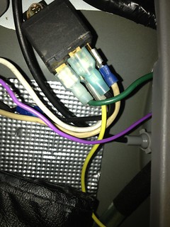
It originally started out as the relay in the diagram posted above, but I ended up changing the blue wire to yellow (needed more length) and the red wire is now off white. I have replaced the relay a few times due to getting it wet or breaking in the past. And it's just a standard configuration SPDT relay.
Btw the lights we're discussing are two 18W LED lamps, so the switch should only need to be rated at 3A+, although the lights the diagram was made for are two 55W halogens. With the exception of the LEDs Ark has and the new one I got, in all instances that I've installed these it has been with the 55W halogens (~9A).
This is a shot I took last night of my backup light relay, the angle isn't the best but you can see all the connections.
It originally started out as the relay in the diagram posted above, but I ended up changing the blue wire to yellow (needed more length) and the red wire is now off white. I have replaced the relay a few times due to getting it wet or breaking in the past. And it's just a standard configuration SPDT relay.
Btw the lights we're discussing are two 18W LED lamps, so the switch should only need to be rated at 3A+, although the lights the diagram was made for are two 55W halogens. With the exception of the LEDs Ark has and the new one I got, in all instances that I've installed these it has been with the 55W halogens (~9A).
Posted By: oldspark
Date Posted: January 07, 2013 at 5:51 PM
TWO CORRECTIONS to MY reply above.
Since it is a not a high power load, I withdraw my stupidity comment. (I consider 3A (36W) not unreasonable for a switch etc; and as a simple add-on to ANY relay type without the complication of diodes that wiring solution has IMO always been brilliant.)
The 2nd correction is more of a clarification:
The diagram shows an SPST relay with dual outputs (2x 87) and that will work fine as per the diagram.
But OP arkansas_mystic stated an SPDT relay in which case it has to be reversed as turboled wrote. IE - #87a from switch, #87 from +12V, #30 to LEDs/lamps.
Hence any SP relay with dual output will work - even a 4 pin with a male/female (2-way) spade connector, eg:

(Courtesy of RKS Sales and Narva)
PS - gaterose - thanks for chiming in!
And sorry to all that I missed the SPDT wiring error (thanks turboled!) else that the diagram specified SPST (which I checked from eg https://www.dodgetalk.com/forums/showpost.php?p=2265467&postcount=17 - thanks Google image search!).
Since it is a not a high power load, I withdraw my stupidity comment. (I consider 3A (36W) not unreasonable for a switch etc; and as a simple add-on to ANY relay type without the complication of diodes that wiring solution has IMO always been brilliant.)
The 2nd correction is more of a clarification:
The diagram shows an SPST relay with dual outputs (2x 87) and that will work fine as per the diagram.
But OP arkansas_mystic stated an SPDT relay in which case it has to be reversed as turboled wrote. IE - #87a from switch, #87 from +12V, #30 to LEDs/lamps.
Hence any SP relay with dual output will work - even a 4 pin with a male/female (2-way) spade connector, eg:
(Courtesy of RKS Sales and Narva)
PS - gaterose - thanks for chiming in!
And sorry to all that I missed the SPDT wiring error (thanks turboled!) else that the diagram specified SPST (which I checked from eg https://www.dodgetalk.com/forums/showpost.php?p=2265467&postcount=17 - thanks Google image search!).
Posted By: KPierson
Date Posted: January 07, 2013 at 6:55 PM
I did not realize that the center pin is marked 87 and not 87A. The blurriness of the picture made it difficult to read. As oldspark Stated that is NOT a SPDT relay, that is an SPST relay with two contacts paralleled to the 87 pin.
As long as your switch is rated at 6A (twice the expected load) the switch would be fine. If it is rated at less then 6A I personally would use the diode method.
-------------
Kevin Pierson
As long as your switch is rated at 6A (twice the expected load) the switch would be fine. If it is rated at less then 6A I personally would use the diode method.
-------------
Kevin Pierson
Posted By: arkansas_mystic
Date Posted: January 07, 2013 at 8:01 PM
Its great to finally have an answer, thanks everyone. I have no experience with relays, so I was thinking all 5 pin relays were SPDT. Another guide I was following also suggested SPDT (it was just wired to a switch, not tied into the reverse circuit) so that is what I went with.
I purchased and installed the diodes a few hours ago, before oldspark posted the reply. Everything is working perfectly. I should have mentioned I'm dealing with leds and not halogens. My switch is rated for 20 or 25 amps, can't remember which. So question is, should I leave it as is with the diodes or do something different? Thanks again!
I purchased and installed the diodes a few hours ago, before oldspark posted the reply. Everything is working perfectly. I should have mentioned I'm dealing with leds and not halogens. My switch is rated for 20 or 25 amps, can't remember which. So question is, should I leave it as is with the diodes or do something different? Thanks again!
Posted By: oldspark
Date Posted: January 07, 2013 at 9:14 PM
I think leave it as is.
And that's not merely just because it works LOL, but more on that below. (IMO there is much wisdom in the old "if it works, don't touch it"!!)
The only consideration might be to drop the 20A fuse(s) to 10A since the load is only 2x18W = 36W = 3A; hence a 5 or 7.5 or 10A fuse, but 10A is common, has adequate headroom above the load, and is (hopefully!) below the switch and wire rating.
(Why do I think the switch is 16A rated? And if so, its fuse should not exceed 16A - ie, 15A. POST EDIT - now I see your 20-25A rating claim... d'oh! )
Certainly do not worry about your 5 pin confusion! I think that is a very common mistake even by the experienced.
Even KP and I missed that one, though I should stress that that was in theory - we would never have wired that way in practice (right Kevin?). Besides, it was obvious that neither of us could read the blurred central normally 87a pin and that we trusted that YOUR SPDT is what was in the diagram. (Hey Kevin, do you think I got away with that one?)
As to me missing the incorrect SPDT wiring that turboled picked up on...
But on that point, turboled's described SPDT wiring is how most such systems are done assuming diodes are not used. The reason is that it isolates the 2 input sources, ie neither are ever connected together but either power the load.
The disadvantage is the short break when the relay changes over, and that NC (#87a) contacts usually have lower current rating than the NO #87 contacts (because of solenoid versus a sprung contact pressure).
Now the optional extra reading on why I think stick with it...
- You now have IMO the ideal configuration. IE - heavy switch current is offloaded to the relay, and the diode circuit does the switching logic instead of the relay. (Hence an SPST relay can be used.)
- You can easily add more LEDs/lights without effecting switch current.
- You have more switch choices, the switch need only handle the relay coil's current and its indicator LED - that's probably up to 250mA instead of its 3A else 5A or higher for halogen lamps.
- As it is now with its heavy switch, you can revert to the diagram if the diodes fail or their joints break.
And all options mean you can use SPST or SPDT relays irrespective of diodes.
With diodes it uses SPST (or an SPDT with 87a unused).
Without diodes it uses a dual-output SPST (whether 5 pin, or 4-pin with spade junction) or an SPDT with #30 to the output(as per turboled).
Of course an SPST relay is an SPDT but not using #87a. [ And for SPST, #30 & #87 are interchangeable. However convention is that coil #86 is +ve and #85 is -ve or GND and that is important only for relays with inbuilt (spike) protection diodes. ]
I mention the last because all the relays I now procure are SPDT types (eg, micro-Iso relays from car wreckers/salvage).
Provided the cost is the same and the base has the 87a slot (whether wired or not), then spare SPDT relays solve all replacements, ie, one part for all SPST or SPDT. (Noting that contact ratings and whether intermittent or full-time use are another issue, and that the base is NOT wired for a dual-output #87 SPST!!.)
Posted By: arkansas_mystic
Date Posted: January 07, 2013 at 10:07 PM
Excellent info oldspark! I started to post a direct link to the wiring diagram, but wasn't sure if that was allowed so I captured the screenshot. It did make it harder to see. From the beginning I assumed the relay in the diagram was a SPDT, so that was my fault entirely.
I will leave everything as is since that's the best way for this to be wired. Also, I do have a 7.5 amp fuse installed, not a 20 amp as in the diagram. I was just using that diagram and modified it to work with the LED's (with a lot of help from gaterose). The only thing we missed was the SPST 5 pin relay.
I will leave everything as is since that's the best way for this to be wired. Also, I do have a 7.5 amp fuse installed, not a 20 amp as in the diagram. I was just using that diagram and modified it to work with the LED's (with a lot of help from gaterose). The only thing we missed was the SPST 5 pin relay.
Posted By: oldspark
Date Posted: January 07, 2013 at 11:43 PM
Ah-ha! So you admit you deliberately posted an inferior pic just to trip us. Well good on you - it's good to keep us on our toes, and to show others that I still miss things (and can hence go off tangentially, though I'll often do that anyhow!).
My first sentence above is (obviously?!) in jest, but the 2nd has its seriousness - ie, this thread contains many clarifications: checking 87a versus dual 87 relays; how to shift the high-current combinational switching to the low current coil side; and how simple transpositions can convert from one solution (or problem!) to another.
[ Note that I said "simple", I did not say "not tricky". But that's part of experience or being able to stand back and consider the circuit, and scratch-padding changes or simplifications. And that's probably easier with my "circuit diagram" approach where f.ex you see the relay contacts rather than the relay body - eg, see capacitor value for latching relay? (2nd last reply on page 1) and compare the upper the 12volt stye wiring pic with my lower circuit style pic - which is easier to understand behavior-wise? But hence the difference between the quick installation answer as opposed to my educative rambles. ]
As to other site's pics, I'd argue a link is safer than a a screenshot. The latter could impinge Copyright and IP (Intellectual Property) etc whereas a link directs to the legitimate source.
That assumes you can link to such, but generally it's only links like eBay that are filtered out here (and IMO rightfully so since they will disappear before long).
However I do prefer such diagrams to be embedded for convenience as you did. I hate having to chase thru links even though I now have reasonable bandwidth and download capacity, and a fast PC.
And I usually expect other forums to be accepting since most are for the benefit of members & readers; they tend not to be commercial and proprietary interests.
Nevertheless I posted the link to the higher-res version of your pic since I could link direct to the relevant post, and (IMO) it overcame any Copyright issues.
Other times I will ask for permission as I did for need input for a 24v led light (3rd post) since it was such a brilliant combinational diagram and saved me drawing something similar. (That fig was from Otherpower's Home Built LED Lighting page and their Executive Director Dan Fink gladly gave permission provided I credited it to Otherpower.com. And that was no problem, in fact I gave Otherpower.com more than mere credit for that - I was very impressed with many of their pages!
Sorry, I have gotten somewhat carried away on that issue which really is one for the12volt's admin etc and not for me to dictate. However I suspect the12volt concurs, and I am somewhat experienced and keen on protecting IP & Copyright whilst still allowing "fair" use, hopefully to the benefit of ALL concerned.
And I thank you for your thanks. Alas that really goes to the12volt - it seems to attract the best. Even these so-called "Junior Member" noobs that think they know little, yet already substitute 7.5A fuses etc.
It's been a pleasure seeing your issue solved, and seeing the help from others including gaterose. Hopefully gaterose can now pinpoint quickly what I expect to be a common problem in non-working installations. (That stops whingers blaming the messenger just because they don't realise it's an implementation problem. Strike One for us!)
Now, since I too need a reversing light on my ute...
Posted By: turboled
Date Posted: January 08, 2013 at 7:21 AM
As a post-mortem, I have a question; Why do we need the relay and diodes?
-We can assume the factory backup light output carries enough current to light the bulbs;
The factory backup light output should carry no current (open state) when not reversing;
-So what could happen if we just connect the switch output to the factory wire, without any diode and relay? Could it damage the OEM electronics when the switch turns on?
-Why the diodes? In that case, I don't see backfeeding as a problem either.
Posted By: turboled
Date Posted: January 08, 2013 at 7:36 AM
Never mind. I now understand that the need was to "add" new backup lights and not power the existing lights with the switch.
Posted By: oldspark
Date Posted: January 08, 2013 at 9:07 AM
Well you made a good point.
If there is no issue with backfeed, then the diodes are unnecessary. EG, if both the manual switch and rev switch are from the same fuse, the backfeed is probably not a problem unless perhaps the rev switch is electronic instead of a plain switch from the fuse.
If say the manual switch were from +12V or ACC and the rev switch from IGN +12V, then cross-connection (backfeed) will effect other circuits. (EG - if from +12V, turn on the manual switch and put the box in reverse and the IGN is powered so you could reverse roll start the car and make a speedy getaway in reverse (assuming no immobiliser etc).
IMO if OR-ing (joining) +12V feeds, then diode-isolate them to ensure there is no cross-connection/backfeed issues - unless you know that has no effect (eg, same fused power and no reverse feed into unpowered electronics).
[ Hence the beauty of a ground switched circuit - just parallel all desired grounded switches; no diodes are required. But note that that is for ONE load, it's not to be confused with a common switch for multiple loads (eg, a manual GND switch for a dome light where its door switch also triggers something else.) ]
BTW - In the +12V switch version we discussed, I liked how using the output of the SPST relay for the manual meant no backfeed, though that requires a full current rated switch & wiring. (And as I said, that negates the advantage of the relay etc, though being only a ~3A load... And as you (turboled) said, that relay may well be unnecessary.)
And isolation is provided in the SPDT version as the load/lamp is powered either by the rev switch, else the manual aka bypass supply.
And I guess I'm just stating the obvious - at least now and in hindsight. But the above connection strategies are the typical ones used for almost any situation. Which on depends on the desire (a simple add on, or thinner cabling, etc).
Incidentally, I'd assume the existing and added lights to be the same. Or at least the added LEDs are on when reversing normally, but maybe only the added LEDs/lights are on in the manual mode (hence no mods to the OEM lights; besides, did you see the pics? - the new LEDs outswamp the existing lights).
I had a similar set up for a 55W halogen reversing light years ago though I also had a disable switch. IE - manual 55W for camping or seeing the body I just hit; normal reversing for city and civilian use, and both for rallying and driving elsewhere.
Actually now that I recall, the manual switch was selectable between +12V, ACC or IGN power, and I had an additional distant switch to ensure the 55W was unbypassable (so it couldn't accidentally be switched on with tailgaters...).
Posted By: turboled
Date Posted: January 08, 2013 at 9:24 AM
oldspark wrote:
IMO if OR-ing (joining) +12V feeds, then diode-isolate them to ensure there is no cross-connection/backfeed issues - unless you know that has no effect (eg, same fused power and no reverse feed into unpowered electronics).
When joining +12V feeds with diodes, I think the relay becomes mandatory just because the diode adds a unavoidable voltage drop to the line, then your +12V becomes +11.3V and you have dimmed lights.
Posted By: arkansas_mystic
Date Posted: January 08, 2013 at 4:07 PM
Gaterose had given me tons of info (such as the 7.5 amp fuse) on this setup, I can't take any credit. I am a total noob at this, and it's the main reason I didn't add auxiliary lighting a long time ago. That's the reason some things were left out or not 100% accurate.
There's been a lot of excellent info posted here, and in great detail. This install have been very beneficial, feels like I've learned quite a bit.
Couple pics of the results (still have some aiming to do):


There's been a lot of excellent info posted here, and in great detail. This install have been very beneficial, feels like I've learned quite a bit.
Couple pics of the results (still have some aiming to do):
Posted By: oldspark
Date Posted: January 08, 2013 at 8:36 PM
Yeah, I'm pretty stoked too. It's refreshed the similar solutions, each perhaps suited to individual situations. And it highlighted the occasional 5-pin SPST relay confusion. (I always refer to the relay body's schematic and apply to circuit-type diagrams. I only learned the 85, 86, 30, 87 & 87a pin convention after a few years on the12volt despite over 30 years wiring heaps of such relays.)
And the clarifications keep coming - like turboled's last about diodes implying a relay - unless the ~0.6V drop is okay for LEDS (because it won't make as much difference as for other lamps) ad you don't mind getting 3A or 5A or 10A whatever rated LEDs.
IMO such things have been covered but they may not be obvious.
And in summary, my general view is to bite the bullet and use common cheap low current diodes (IN400x) and a simple SPST relay (or rather, your "standard" spare universal SPDT relay with its 87a unused) and hence no isolation issues, no voltage drops and minimal high-current wiring and fuses. (Exception - if 2 different power sources for the load/lamps are used (maybe for redundancy?), but then either a "reverse" SPDT relay though I instead prefer the SPST off a fused +12V supply.)
All that could be extracted and rewritten in an easier reading hierarchical post.
And finally, I am impressed by the result. That's a brilliant (pun intended) reverse light. And to think it consumes less power than the standard bulbs (ie, 2x18W vs 2x21W etc) - IOW, a straight substitution would lessen the "strain" on the OEM switch yet produce far superior lighting.
LEDs have and certainly will revolutionise lighting.
I'm waiting for LED headlight prices to drop, then I'll do a halogen to LED migration and bypass all the hassles with HIDs.
As to the brilliant warm white light from my dome LED, never again will I use a tungsten festoon etc bulb!
Posted By: arkansas_mystic
Date Posted: January 08, 2013 at 8:46 PM
I actually worked for Radio Shack for several years, and although we carried diodes, relays, and switches, I never knew anything about them. After the info in this thread, it's easy to see how they all work together and the reasons for using them, would have been nice to know that back then.
The LED reverse lights are a spot pattern, so there is a dim spot in the middle. I plan to switch them out for the same lights in a flood pattern (flood wasn't available when I ordered). I'm in love with the LED's, the amount of light they throw is unbelievable. That's only the rear, the view from the front is even better.

The LED reverse lights are a spot pattern, so there is a dim spot in the middle. I plan to switch them out for the same lights in a flood pattern (flood wasn't available when I ordered). I'm in love with the LED's, the amount of light they throw is unbelievable. That's only the rear, the view from the front is even better.
Posted By: arkansas_mystic
Date Posted: January 08, 2013 at 8:49 PM
arkansas_mystic wrote:
I actually worked for Radio Shack for several years, and although we carried diodes, relays, and switches, I never knew anything about them. After the info in this thread, it's easy to see how they all work together and the reasons for using them, would have been nice to know that back then.
The LED reverse lights are a spot pattern, so there is a dim spot in the middle. I plan to switch them out for the same lights in a flood pattern (flood wasn't available when I ordered). I'm in love with the LED's, the amount of light they throw is unbelievable. That's only the rear, the view from the front is even better.
Not sure why that pic didn't work. As a noob, I can't edit my post so I'll try again. It's a 30" double row LED bar on the front.