two spdt rocker spdt relay wiring diagram
Printed From: the12volt.comForum Name: Relays
Forum Discription: Relay Diagrams, SPDT Relays, SPST Relays, DPDT Relays, Latching Relays, etc.
URL: https://www.the12volt.com/installbay/forum_posts.asp?tid=133595
Printed Date: May 14, 2026 at 4:07 AM
Topic: two spdt rocker spdt relay wiring diagram
Posted By: ebb tide
Subject: two spdt rocker spdt relay wiring diagram
Date Posted: February 14, 2013 at 3:29 PM
Two boat mast lights switched with circuit breakers in main cabin. Will add a switch in bow and aft berth to turn on one or the other light not both. Mast lights terminal board is in the bow berth ceiling. 12v fused source nearby. Will add bow carling contra two led spdt on-off-on rocker sw and spdt 20a relay. 15ft. Aft 20g wire to aft berth add carling contra spdt on-off-on. Best wire scheme for this added function with new sw & relay?Archives,2011 hot water wizard made wire diagram for a guy for two dome lights with power source at dome lights. Mast lights don't have power source. Be aware I know nothing about electricity. Thank you for your consideration and your discretionary time to address this issue.
-------------
Ebb Tide
-------------
Ebb Tide
Replies:
Posted By: oldspark
Date Posted: February 14, 2013 at 4:35 PM
If the mast lights don't have a power source, why the circuit breakers in the main cabin?
Two switch circuits are common, eg here and here.
[Note that what I and the second link call a 2 way switch (as in SPDT - Single Pole, Double Throw ( = position or "way") the first calls a 3 way switch because it has 3 terminals. The latter appears to be common with AC building electricians and often causes great confusion for anyone else.]
{Trivia: That first link has a "current flow" animation that shows electron flow. It should show "conventional current flow" which is in the opposite direction. Not that that is important, but feel free to quiz that if ever you get into discussions or arguments about whether current is electron (or ion) flow. FYI - it can be either or both electrons (& -ve ions) or +ve ions - ie, charged particles, but electricity is more than the flow of either, ie charged particles flow as a result of electricity (though their movement also causes electricity.}
Those switches could energise a relay instead of the light(s) directly, and relays may be simplest for your "only one of two" requirement - especially if located close to each other.
Note that you could switch the -ve or GND path instead of the +ve if shorts are a concern, but it must then be moisture proof to ensure a relay doesn't come on when not switched. The same applies for the +ve switch wiring but its chances are less assuming local grounded metal.
[Relays require relatively small current to energise and plain water can be enough. They might so "short" via external terminals (to an external GND) or between internal conductors.]
If by the mast lights not having a power source you mean that their power is internal, then relays are probably best - ie, to break the internal power.
However if power conservation is important, then switches may be best - each energised relay may require 60mA to 250mA (0.7W to 3W) which may be significant, especially if using LEDs etc.
Relays are generally used to take the heavy current off switches and minimise heavy cabling (the switch to relay coils can be light cable) or to localise power switching from remote "controlling" locations.
They can also be used to simplify switch types - eg, an on-off SPST switch can control a 2 way SPDT relay, or relays can do the "logic" or combinational switching (eg, if you want two 2-way switches for each of 2 lights but only one light to be on, then DPDT relays might be used).
Sorry if the above confuses you, but I'm not sure of your full setup (distances, LEDs, power source & capacity, etc). However I'm sure we'll get a suitable & elegant solution (meaning cheap & reliable and apparently simple).
Posted By: howie ll
Date Posted: February 15, 2013 at 6:33 AM
Not until we see a layout diagram I'm afraid, anyway if they are LEDs why the relays?
Is this switch momentary or latched?
Off topic Peter, because your PM in-box is full, lazy OZ, a Thatcham Cat I alarm such as the Clifford G5 series, draws 20 milliamps when armed including the LED.
I can't remember the the thread where that came up recently.
-------------
Amateurs assume, don't test and have problems; pros test first. I am not a free install service.
Read the installation manual, do a search here or online for your vehicle wiring before posting.
Posted By: ebb tide
Date Posted: February 15, 2013 at 8:13 AM
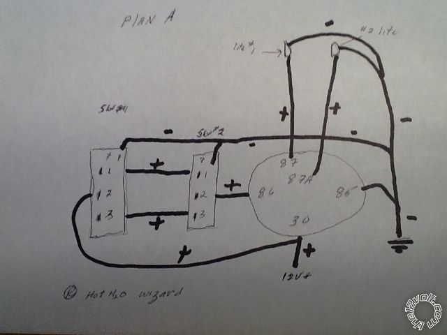 the basis for this wire diagram is hot water wizard's john deRosa response to a ? On 12Feb. 2011.
 "mast lights not having power source". Poorly stated on my part. I mean to say. When mast lights are turned off at the circuit breaker panel in the main cabin. A multimeter detects no voltage at the mast base terminal block in the ceiling of the bow berth.
The mast lights are not led.
Sw #1 is 15+feet from sw#2. With relay nearby sw#2, 12v +power source and mast light terminal block can run light weight 20g signal wire for travel wire to a distant sw#1. Will use 14g +12v power source to pin 30, 87+ to light #1,87A+to light#2, 86 - to gr. ,light #1and 2 - to gr.
Relay is 40a weather proof, area of placement is enclosed dry space not exposed to elements.
Hope this is helpful. Please understand I'm way over my head on this project, i know little about electricity. My success is depend on your generosity in sharing your knowledge and experience. For which I thank you.
-------------
Ebb Tide
Posted By: oldspark
Date Posted: February 15, 2013 at 8:32 AM
That diagram, means that the #2 light will be on when #1 isn't.
The only way to turn #2 off is by turning off the +12V supply, but that may be your intention.
Note that the -ve wires do not have to go to the 2-way switches - only the relay #85 & the light GNDs or -ve's.
Actually it's not a bad setup assuming that when the breaker in the cabin is on, #2 is the "default" light. But if you
toggle (flip) either light switch, #1 comes on instead.
The relay only draws its (coil) power when #1 is turned on (ie, +12V thru BOTH switches for +12V across the relay coil (+12V to #86, and #85 is 0V aka GND) which energises the relay and flips the light power (#30) from #87a to #87.
I'd suggest having the relay box accessible in case the relay contacts fail. If only the coil fails, then #2 will remain lit (assuming good #30 to #87a contacts.
Again, I hope I haven't confused you.
But reply if you have questions or concerns.
Happy boating!
PS - the "no power source" is cool. I was confused, but you stated the obvious - if "power" (+12V) is disconnected (because of an open switch or circuit breaker or fuse etc) then there will be no voltage on the "downstream" side (because the grounded loads (lights) pull their +ve ends to 0V aka GND voltage).
Of course, it is always worthwhile checking that the above is true. If there is "voltage" on the downstream side, there may be a problem - ie, feed-thru from other sources.
[ Though not usually an issue for 12V etc DC systems, it can be a fatal mistake on 120V & 230V AC systems. EG - The use of AC UPSs (Uninteruptible Power Supplies) often caused the isolated (turned-off) downstream side to still be live (usually at ~60VAC ~& 115VAC respectively for 120V & 240V AC UPSs) - much to the shock of firefighters and electricians... ]
Posted By: ebb tide
Date Posted: February 15, 2013 at 2:00 PM
Oh my,will need to change wiring and or add another relay. But first why am I doing this project? When boat is in a marina slip frequently folks walking the dock day or night will pause and comment on the characteristics of each boat while assuming the boat is unoccupied and they are not disturbing others. I wish to turn on a deck light as signal that we are on board and are aware of their presence. It would sure be nice to turn a deck light on or off from one of the births and have to get up and go to the circuit panel in the main cabin. Sooo...
Wish to turn on or off light# 1 or light#2 from either switch. Panel circuit breaker is off.
Carling contra spdt rocker switch with led on position indicator light.
Each switch has 3 positions all latched. On. Off. On no (momentary) each switch has 4 pins
1 ve+ out. 2 ve+ in 3 ve+ out 7 ve-
Position 1 on 1-7 are closed led is on
Position 2 off. Circuit off and no led
Position. 3. On. 3-7 closed and led is on
Sorry, I should have clearly stated why I had ve- to each switch.
Sadly I have no idea how to wire the spdt relay such that we can turn on or off either light from each switch.
The relay is accessible - it is beside the bow berth bed behind access Door.
Will have 12v+ power source connected to a hidden toggle switch.
Note boat guest like to fool with boat switches ...batteries drain fast .
So how the heck does a guy wire this thing?
BTY old-spark last month we were in Australia cruised to and around NZ.
Sidney was so very hot. Numerous horrible out of controller fires..
-------------
Ebb Tide
Posted By: howie ll
Date Posted: February 15, 2013 at 3:30 PM
This is the elegant answer Oldspark was waiting for;
Single tone proximity detector or infra-red sensor linked to a 528t timer relay instead of the original relay, auto turn on for 90 seconds.
-------------
Amateurs assume, don't test and have problems; pros test first. I am not a free install service.
Read the installation manual, do a search here or online for your vehicle wiring before posting.
Posted By: oldspark
Date Posted: February 15, 2013 at 4:51 PM
LOL - I thought Howard was talking about ebbtide's reply (which had the all useful background info), and ebbtide was talking about Sydney (Orstralia)... or is ebbtide working thru a proxy or - often like me - using a decoy location?
I'm in Melbourne and we're having a nice mild 33C today, but no major fires that I am aware of.
Howard's suggestion is the type of elegant answer I thought of once I read your (ebbtide's) reason for the wiring. In fact I'd probably consider an optional extra for loud or irritating people - a loudness else remote triggered zapper eg, a 50-cal or maybe rail gun.
My only concern is the drain that such detectors may cause. And railguns are hard on batteries - but unlike 50-cals are silent so you won't disturb others. Others are concerned about the legalities of blowing away inconsiderate people, and they have every right to express those concerns. I however would only be concerned about blowing away minors or people from cultures where loudness etc is considered to be a compliment.
Luckily power conservation and batteries is something I am quite familiar with. And being a local invention, so too rail guns (though I think it was Tesla that invented Transformers).
Now, I won't be available for a few days, but in the meantime, some thoughts & considerations:
Don't worry about lack of electrical knowledge. It can usually be thought of as water traveling thru pipes etc except that it must be cyclic - ie, travel in a complete loop. It's as if we have a sealed water system where the water returns to its original tank (battery or generator) and can't go anywhere else - it can only go thru valves and pipes and sealed attachments.
Oh - and electricity can hurt and kill if its pressure (voltage) is high enough. And while water might put out fires, electricity can start them.
But that knowledge shouldn't matter in this case.
Conversion to LEDs will save a lot of power. They typically consume far less than than one-twentieth of equivalent tungsten etc lights.
What is your battery size (AH) and how long between recharges?
Is it one battery or more?
Is recharging from an onboard source (engine, generator, solar)?
Is the battery critical for other things like engine cranking? (I'm thinking here of battery protection or low-voltage cutoust etc else a dual-battery etc. Or if not rechargeable onboard, the need for emergency comms etc.)
And your financial situation? (I'd assume somewhat lacking being as boat owner - "a boat is a hole in the water into which one pours endless money" or something like that.) IE - are you keeping it to what you've got plus the odd wiring and relay costs?
When it comes to battery costs & replacement, LED conversion may be a worthwhile money-saving investment (which also requires lighter cabling), but that can be considered later though it could change things if done now (eg, maybe ignore the existing set up and simply add the new LEDs on a separate (timed) circuit since their additional power draw should be relatively low).
Sorry if this reads poorly - I'm rushing to get elsewhere (I can hear my partner complaining...).
And sorry if my humour(??!) is a bit off.
I should be back in a few days.
PS - thanks for explaining the grounded switches. I withdraw my earlier comment, and I'll consider further before our next chat.
Posted By: howie ll
Date Posted: February 15, 2013 at 5:10 PM
Have a nice trip Peter but I caught your deliberate (I hope) error.
Voltage kills????
-------------
Amateurs assume, don't test and have problems; pros test first. I am not a free install service.
Read the installation manual, do a search here or online for your vehicle wiring before posting.
Voltage kills????
-------------
Amateurs assume, don't test and have problems; pros test first. I am not a free install service.
Read the installation manual, do a search here or online for your vehicle wiring before posting.
Posted By: ebb tide
Date Posted: February 17, 2013 at 8:05 AM
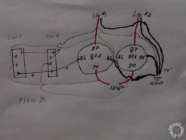 This arrangement will allow for controlling either light from each switch. The main cabin breaker panel remains functional
Thanks to those providing pertinent guidance, your efforts are appreciated. Cheers.
-------------
Ebb Tide
Posted By: oldspark
Date Posted: February 18, 2013 at 6:18 PM
Thanks for the thanks.
Addressing Howard's "voltage kills?", I just kept it simple. I know it's current thru the heart that kills and that takes ~10mA for stoppage and (usually worse) 1mA to 10mA for fibrillation.
The voltage required varies. It might be a few volts or less during surgery, or mains voltages for normal people, or higher for wet people.
Of course extreme current can fry the entire system and the heart is irrelevant. (Where that youtube link to the person they gets "petrified" on a train roof?)
Posted By: howie ll
Date Posted: February 19, 2013 at 2:36 AM
Try "The Darwin Awards".
But that would have been 25kVAC.
LOWER current for wet persons.
-------------
Amateurs assume, don't test and have problems; pros test first. I am not a free install service.
Read the installation manual, do a search here or online for your vehicle wiring before posting.
But that would have been 25kVAC.
LOWER current for wet persons.
-------------
Amateurs assume, don't test and have problems; pros test first. I am not a free install service.
Read the installation manual, do a search here or online for your vehicle wiring before posting.
Posted By: oldspark
Date Posted: February 19, 2013 at 3:45 AM
Ah - but wet people have a conduction path AROUND them, hence at a given voltage, less current through their core.
Applies to both AC & DC - viz: lightning striking wet versus dry people.
(Of course, being wet is more likely to attract the lighting strike... And not that I advise water as protection. I'll keep it mice an ambiguous - electricity kills. That doesn't mean it doesn't kill, and for the old favorite of questions - what is electricity - ie, name it's unique parameter or unit?)
And sorry ebb tide - we are hijacking and/or having fun. But since the thread is closed... (??).
And BTW, I like the ebb tide name. &
& 
Applies to both AC & DC - viz: lightning striking wet versus dry people.
(Of course, being wet is more likely to attract the lighting strike... And not that I advise water as protection. I'll keep it mice an ambiguous - electricity kills. That doesn't mean it doesn't kill, and for the old favorite of questions - what is electricity - ie, name it's unique parameter or unit?)
And sorry ebb tide - we are hijacking and/or having fun. But since the thread is closed... (??).
And BTW, I like the ebb tide name.
&