double check illuminated entry circuit
Printed From: the12volt.com
Forum Name: Relays
Forum Discription: Relay Diagrams, SPDT Relays, SPST Relays, DPDT Relays, Latching Relays, etc.
URL: https://www.the12volt.com/installbay/forum_posts.asp?tid=133863
Printed Date: April 18, 2026 at 6:47 AM
Topic: double check illuminated entry circuit
Posted By: die frau
Subject: double check illuminated entry circuit
Date Posted: March 15, 2013 at 10:25 AM
I was hoping that some of you would do me a favor and look over this schematic and double check my work. I think I am close to figuring this out, but I wanted to be sure I was not about to short something or create an undesired side effect or parasitic drain. I have been pouring over this site and the schematics in the shop manual for a few days.
The vehicle is a 2002 VW Jetta Wagon. The goal is to add Perimeter Lighting / Illuminated Entry to the factory alarm, using the Dome Light (+) as a Trigger. However, the Ignition would interrupt this signal, so if the dome light was triggered from a door being opened while the car was on, there would be no change to the exterior lights.
The reason I would like to use relays, and the dome light trigger is because I would like the lights to mirror each other. If I used a device like the PAC-TR7 or the DEI 528T, there would be an additional timer for the lights that would not be synchronized with the factory alarm, specifically when the alarm Times Out and Re-Arms for instance, if the alarm times out, and the car locks, 60 seconds after the Un-Lock signal from the Fob I would like the exterior lights to turn off at that time. If the alarm is re-armed via the Fob I would like the exterior lights to turn off at that time. If the door/hatch is opened, regardless of the Fob activity I would like the exterior lights on, just like the interior dome light would be.
I am choosing to switch the Left & Right Low Beam in Front and the Reverse Lights in the Rear. The headlights are pretty much self explanatory. I am choosing the reverse lights instead of the parking/running lights primarily because the audible chime used to remind you that your lights are on when you open the door is tied to the parking light circuit. There is probably a way around this, but it would involve some rewiring at the instrument cluster, and additional Diods & Relays, I think. At any rate the reverse lights are brighter and the circuit less complicated.
Some of these connections can/will be made at the fuse panel instead of the location listed, but oddly enough the schematics dont really call out terminal pin locations at the fuse panel, just the fuse number itself. Also my Electrical Engineer Father (apple fell FAR from that tree) pointed out my Relays should be labeled K1, K2 & K3 not- A, B & C and I also need to add a Rev Level, Key, Date and Signature LOL.
Relay A (or K1) takes the Dome Light signal (30) and passes it onto the other relays while ignition is off (87a). When the ignition signal is added, the dome light signal is broken. Relay B (K2), if there is no Dome Light Signal (85) then the connection from the Light Switch (87a) to the Low Beam Bulb Fuse (30) is closed and the switch will work as normal. If there is a Dome Light signal (85), then the Constant Power (87) (Bypass the Headlight Switch) to the Low Beam Bulb Fuse (30) is closed. Relay C (K3), if there is no Dome Light Signal (85) then the connection from the Reverse Switch (87a) to the Reverse Bulbs (30) is closed and the switch will work as normal. If there is a Dome Light signal (85), then the Fused Reverse Power (87) (Bypass the Reverse Switch) to the Reverse Bulb is closed (30).
So
anyone have any input before I let the Magic Smoke out? :D Thanks for your help!!!

------------- -Pete
Replies:
Posted By: howie ll
Date Posted: March 15, 2013 at 3:42 PM
That blue /white dome feed is a switched NEG and the constant 12v+ POS feed is timed for 10 minutes, so 10 minutes after IGN off no power anyway for a start so back to the drawing board for you, sunshine.
Now tell me what you want to do and I'll give you a better way.
Are you trying to bring on both reverse and headlamps Hi and Lo when the alarm triggers?
I'll give you a clue, alarm POS trigger wire is yellow/black I'll confirm that shortly.
-------------
Amateurs assume, don't test and have problems; pros test first. I am not a free install service.
Read the installation manual, do a search here or online for your vehicle wiring before posting.
Posted By: die frau
Date Posted: March 15, 2013 at 4:19 PM
Thank you for looking this over - I will have to look things over and confirm if you are correct.
I am fairly certain that the Dome trigger is Positive. This is the Pos wire that comes out of the Comfort Control Module and goes to the Front and Rear Dome Lights - There are 2 Positives, 1 Negative. The switch on the light has 3 positions - On, Off, Door
Anyway, if it is not - then I will modify the first relay as such:
85: 12V + IGN
86: Ground
30: Dome -
87a: To Position 85 on Relay B & C
87: Open
Then just switch 86 on Relay B & C to 12V + Constant.
I will double check the 10 minute Time Out of the Ignition Power - But it is not too hard to find an always live 12V + Source on the Fuse/Relay Panel. ------------- -Pete
Posted By: howie ll
Date Posted: March 15, 2013 at 4:33 PM
You're wrong I've done a gazzilion alarms on these, its NEG, constant 12V+ unswitched RED / blue and constant (unswitched) NEG brown.
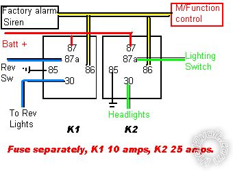
lights_with_alarm.bmp
Much simpler and failsafe.
For K2 use WHITE/ green as Lo or YELLOW /GREEN as Hi at the switch.
If you use both you will need another relay fused at 25 amps. ------------- Amateurs assume, don't test and have problems; pros test first. I am not a free install service.
Read the installation manual, do a search here or online for your vehicle wiring before posting.
Posted By: howie ll
Date Posted: March 15, 2013 at 4:41 PM
Errata, I said blue/white going on memory, but yes it's blue/grey NO it's still NEG, checked via Directwire, although you may have the headlights correct as yellow/red the colours I gave are UK market Wolfsburg build, but hey this car, aka Golf, Rabbit, Vento Beetle plus Seat and Skoda variants can come from Germany, US, Mexico, Brazil, South Africa, China.
But that blue/grey is STILL NEG!
-------------
Amateurs assume, don't test and have problems; pros test first. I am not a free install service.
Read the installation manual, do a search here or online for your vehicle wiring before posting.
Posted By: die frau
Date Posted: March 15, 2013 at 4:55 PM
You are most likely correct - I must have misread the Bentley schematic.
Assuming it is Neg - could I just change the Grd on K2 and K3 to Constant 12v + to achieve the same effect? I would think so.
Regarding the headlight yellow/red - there was a difference in the Golf vs. Jetta Headlights - on the Jetta, they do not have the YELLOW /GREEN wire - only the yellow/red which goes to the headlight dimmer switch (hi/low beam).
The idea is to have the Low Beams in Front and Reverse Lights in Rear Mimic the Dome Light activity when the car is off. When you unlock the car with the Fob or Open the Door, the exterior lights come on, as the dome light normally does, etc.
-------------
-Pete
Posted By: die frau
Date Posted: March 15, 2013 at 5:03 PM
I am looking over the drawing you posted - I understand this would be the case if you wanted the lights to come on if the alarm is triggered - but this is not my goal.
My goal is to have perimeter lighting when you unlock the car, like the interior lighting that already exists.
-------------
-Pete
Posted By: howie ll
Date Posted: March 15, 2013 at 6:36 PM
Still pretty simple the blue/grey is the NEG trigger two relays, job done.
BTW don't relay on just brown wires and always TEST.
Next to the comfort/multifunction module is a major grounding point under the steering column between the column and the module.
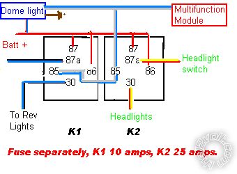
55F_lights_with_alarm.bmp
This will operate EXACTLY as the dome light. Shame about your battery though think it through. ------------- Amateurs assume, don't test and have problems; pros test first. I am not a free install service.
Read the installation manual, do a search here or online for your vehicle wiring before posting.
Posted By: die frau
Date Posted: March 15, 2013 at 7:17 PM
Yes - that is what I was thinking, but have the dome trigger go through another relay to be switched by the ignition. So the two relays in your diagram would be inoperable while the car was on.
For a 12V newbie - can you elaborate on the battery comment? Many aftermarket alarms and cars (including my 2008 Mercedes) have this feature with no ill effects... And I don't think there will be any energized relays or other drains while the car is left alone. Please enlighten me!
I really do appreciate all your help!!! Thank you.
-------------
-Pete
Posted By: oldspark
Date Posted: March 15, 2013 at 9:02 PM
And hence came the day I realised puddle lights were a brilliant idea.
(They are totally unrelated to the under-lighting bling that I was confusing them with!)
Posted By: howie ll
Date Posted: March 16, 2013 at 2:47 AM
The blue/grey is already ignition controlled in the sense it will shut down immediately with door closed and ignition on (actually about 1 second).
What if you're working on on the car, do you want those lights on for 10 minutes?
Hence my battery coments.
I would insert a 528t set to say 30 seconds or 1 minute then daisy chain 1 relay for the second circuit off that, diagram later I've some work for this morning. (Nearly 8:00 am in the UK).
-------------
Amateurs assume, don't test and have problems; pros test first. I am not a free install service.
Read the installation manual, do a search here or online for your vehicle wiring before posting.
Posted By: howie ll
Date Posted: March 16, 2013 at 7:30 AM
More thoughts. Set the timer on the 528t for up to 1 minute.
I've used these relays as "interruptors/changeovers".
The reason being I believe you are feeding back into the ignition circuits. I might be wrong and if so try it by applying a fused 12Volt constant feed to both blue/black rev wire and RED / yellow h/light wire, not at the same time! If there's a tiny spark and the lights work without any ignition light-up you're good to go and you can substitute an 87b relay for the lower two relays.
You could take it a stage further and cut the yellow 528t out put wire via an ignition controlled relay, 5 amp mini PCB or mini cube relay, ign. to 86
ground to 85 528t to 87a relay side to 30.
-------------
Amateurs assume, don't test and have problems; pros test first. I am not a free install service.
Read the installation manual, do a search here or online for your vehicle wiring before posting.
Posted By: howie ll
Date Posted: March 16, 2013 at 9:19 AM
If the above works you can use a double separated make relay type 87b.
Here's a part number from Tycho:-
5-1393304-6 U0/1 Form U
-------------
Amateurs assume, don't test and have problems; pros test first. I am not a free install service.
Read the installation manual, do a search here or online for your vehicle wiring before posting.
|