delayed relay
Printed From: the12volt.comForum Name: Relays
Forum Discription: Relay Diagrams, SPDT Relays, SPST Relays, DPDT Relays, Latching Relays, etc.
URL: https://www.the12volt.com/installbay/forum_posts.asp?tid=133978
Printed Date: February†23, 2026 at 2:19 PM
Topic: delayed relay
Posted By: myonus
Subject: delayed relay
Date Posted: April†03, 2013 at 5:03 PM
<"Times New Roman">G'day, mate!
<"Times New Roman" >
<"Times New Roman">I am putting together post that involves a specific question, but by asking- that requires a little story of my application. And since you were may be aware of my angle of unorthodox electronics, I hoped you could get a sense of the project with what I have so far. Because in actuality, a lot of the parts are still in route from Hong Kong, and I'm just doing preliminary designing. My current focus is the main PCB that will house several components on one board. There are still some cloudy details that obviously need to get on the design, but itís just me, so I'm taking my time not to get too overwhelmed. The way I have been organizing things is the "one circuit board at a time" method. So I donít get ahead of myself. The most recent accomplishment was to successfully breadboard and successful operation of the Dual Light Organ.
<"Times New Roman" >
<"Times New Roman">Dual Light Organ- this is a modified design of a LM324/ 2n4401 circuit. It takes an analog sound signal and amplifies it through a mic/ then feeds it into a NPN transistor to make the LED bounce to the audio in the car. Whether itís from the radio/ mp3 ETC. Even ambient sound or conversations in the vehicle.
<"Times New Roman" >
<"Times New Roman">Instead of it lighting up 2 or in the modified version (4) LEDs it will go to a photo resistor that will operate a gate or another relay (not quite sure yet how itís going to work) to have a output of 20 3mm Ultra-brites, powered by a voltage regulated circuit designed for the specific LED load. These LEDs will be bundled into 4 groups of (5) LEDs. They will each have a small tweak variable resistor to trim the intensity. And a band pass filter to define its response to designated And a clear color gel at the end giving it a color defined by the placement. In this example: Red pulsating light tuned to mid-range and treble set next to the power cable so it appears to pulse power to the amp to the beat of the music.
<"Times New Roman" >
<"Times New Roman">the voltage regulators are for 12v car audio. And all my circuit designs are for 12v and under. My main question is the relay system.
<"Times New Roman" >
<"Times New Roman">I will have a mini power distribution system coming from the battery source and triggered active by the remote signal. So it will only feed if the car is on. that signal will then go to a fuse/ cap circuit before heading to the voltage regulator. Each voltage regulator is 1-40v variable tweak potentiometer. After that it will hit a real-time 3 segment voltage monitor display. Then it will go to a distribution block and out to the wiring end > at the LED.
<"Times New Roman" >
<"Times New Roman">i think it will timeline like this:
<"Times New Roman" >
<"Times New Roman">Battery> fuse > relay >voltage regulator > monitor > crossover/ trim > LED
<"Times New Roman" >
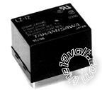
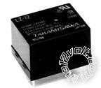
<"Times New Roman">I know to use one of those big ass black relays for the battery connection things that draw more than the source. But I donít want 6 of these monster units on my PCB. I have a drawer full of little PCB mount relays ( blue with different values ) can I use these on my PCB to send these little Accessories 5v @ 2A and keep their power drain more managed? or do I have to use that big, fat, ugly, space wasting, eye sore, wife of mine? ........................I mean relay.
<"Times New Roman">
<"Times New Roman">
-------------
Be not guided by morality, but rather, integrity.
Replies:
Posted By: myonus
Date Posted: April†03, 2013 at 5:06 PM
G'day, mate!
I am putting together post that involves a specific question, but by asking- that requires a little story of my application. And since you were may be aware of my angle of unorthodox electronics, I hoped you could get a sense of the project with what I have so far. Because in actuality, a lot of the parts are still in route from Hong Kong, and I'm just doing preliminary designing. My current focus is the main PCB that will house several components on one board. There are still some cloudy details that obviously need to get on the design, but itís just me, so I'm taking my time not to get too overwhelmed. The way I have been organizing things is the "one circuit board at a time" method. So I donít get ahead of myself. The most recent accomplishment was to successfully breadboard and successful operation of the Dual Light Organ.
Dual Light Organ- this is a modified design of a LM324/ 2n4401 circuit. It takes an analog sound signal and amplifies it through a mic/ then feeds it into a MPN transistor to make the LED bounce to the audio in the car. Whether itís from the radio/ mp3 ETC. Even ambient sound or conversations in the vehicle.
Instead of it lighting up 2 or in the modified version (4) LEDs it will go to a photo resistor that will operate a gate or another relay (not quite sure yet how itís going to work) to have a output of 20 3mm Ultra-brites, powered by a voltage regulated circuit designed for the specific LED load. These LEDs will be bundled into 4 groups of (5) LEDs. They will each have a small tweak variable resistor to trim the intensity. And a band pass filter to define its response to designated And a clear color gel at the end giving it a color defined by the placement. In this example: Red pulsating light tuned to mid-range and treble set next to the power cable so it appears to pulse power to the amp to the beat of the music.
the voltage regulators are for 12v car audio. And all my circuit designs are for 12v and under. My main question is the relay system.
I will have a mini power distribution system coming from the battery source and triggered active by the remote signal. So it will only feed if the car is on. that signal will then go to a fuse/ cap circuit before heading to the voltage regulator. Each voltage regulator is 1-40v variable tweak potentiometer. After that it will hit a real-time 3 segment voltage monitor display. Then it will go to a distribution block and out to the wiring end at the LED.
i think it will timeline like this:
Battery> fuse > relay >voltage regulator > monitor > crossover/ trim > LED
I know to use one of those big ass black relays for the battery connection things that draw more than the source. But I donít want 6 of these monster units on my PCB. I have a drawer full of little PCB mount relays ( blue with different values ) can I use these on my PCB to send these little Accessories 5v @ 2A and keep their power drain more managed? or do I have to use that big, fat, ugly, space wasting, eye sore, wife of mine? ........................I mean relay..

-------------
Be not guided by morality, but rather, integrity.
Posted By: oldspark
Date Posted: April†04, 2013 at 1:19 AM
You use as many relays as needed, and as long as each relay is rated to handle the required current, and its coil is of suitable voltage (ie, the trigger voltage, or less with a series resistor).