multiple video screens
Printed From: the12volt.com
Forum Name: Relays
Forum Discription: Relay Diagrams, SPDT Relays, SPST Relays, DPDT Relays, Latching Relays, etc.
URL: https://www.the12volt.com/installbay/forum_posts.asp?tid=134121
Printed Date: April 18, 2026 at 6:02 AM
Topic: multiple video screens
Posted By: gec123
Subject: multiple video screens
Date Posted: April 29, 2013 at 9:30 AM
Hello All,
I have a 2009 Mazda 6 that I am installing multiple video screens into. The car has 2 outlets for 12 volt power one that is accessory and one that is constant. A few months ago I wired in a flip down monitor and reverse camera using the accessory. This weekend I tried to install to head rest monitors with a video amp/splitter and used the same source of accessory power but kept blowing the fuse. It worked for one headrest monitor but as soon as I did the other one the fuse would go. The same thing would happen, I could run the headrests with no problem but if I turned on the flip down then it would go out. So after some reading I figured out I was over my amperage and was causing the fuse to pop. I'm a newbie, but hey I'm learning.
My thought is to use the constant 12volt outlet but obviously I don't want to slowly drain the battery, so looking to turn that source of power into an accessory line and research has led me to relays. I have never used one before, but looking at different diagrams it seems this is a good solution to provide separate power to the headrest monitors and video amp. I am sure this is probably basic stuff for most of you, but would appreciate any assistance. Thank you!!!
Replies:
Posted By: oldspark
Date Posted: April 29, 2013 at 9:48 AM
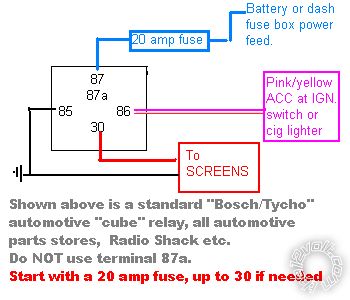
Use a relay.
GND to 95
IGN +12V or ACC +12V to 86
battery thru fuse to 30
87 to screens.
The fuse should be rated for about 1.3 times the load current or more, and less than the smallest rated cable from that fuse.
Posted By: howie ll
Date Posted: April 29, 2013 at 10:07 AM
This simple:- relay_for__extra_loads.bmp------------- Amateurs assume, don't test and have problems; pros test first. I am not a free install service.
Read the installation manual, do a search here or online for your vehicle wiring before posting.
Posted By: howie ll
Date Posted: April 29, 2013 at 10:10 AM
I see my antipodean friend beat me to the punch in my diagram. I've used 87 as the input and 30 as the output, he is correct but it doesn't matter in practice.
By the way he also means 85 not 95.
-------------
Amateurs assume, don't test and have problems; pros test first. I am not a free install service.
Read the installation manual, do a search here or online for your vehicle wiring before posting.
Posted By: howie ll
Date Posted: April 29, 2013 at 10:12 AM
Peter how about answering this one "flash to pass and dip/main relay"
I don't think it's possible unless you use a pickaxe or similar.
-------------
Amateurs assume, don't test and have problems; pros test first. I am not a free install service.
Read the installation manual, do a search here or online for your vehicle wiring before posting.
Posted By: gec123
Date Posted: April 29, 2013 at 12:57 PM
Thank you all very much for helping me. I went to Autozone and picked up a Duralast Relay part # 19208. It is similar to what you have in the Diagram Howie (perfect btw) accept the left side says 86 and the right is 85. Is 85 still the ground and 86 the Acc?
howie ll wrote:
This simple:-relay_for__extra_loads.bmp
Posted By: howie ll
Date Posted: April 29, 2013 at 1:54 PM
Yes, I just move them to make the diagrams easier to draw!
In ISO convention:
85 = coil negative
86 = coil positive
87 = output can be input
30 = input can be output
87a NC connected to 30
When using as a changeover rather than switch 30 is used as the output, although your use is effectively as a switched current amplifier.
-------------
Amateurs assume, don't test and have problems; pros test first. I am not a free install service.
Read the installation manual, do a search here or online for your vehicle wiring before posting.
Posted By: oldspark
Date Posted: April 29, 2013 at 11:11 PM
Howard - Thanks for the GND 95->85 correction. (I got the important digit right didn't I?... rats!)
And I just looked for the 2nd time at flash to pass and dip/main relay Funnily enough, I'm still not in the mood, but I did expect others to answer. I'll consider it later... (kick me...).
As I just wrote in another thread:
Interchanging the relay input and outputs does not matter - ie, 87 or 87a & 30. (In SPST situations.)
I often connect the output loads from 30 with its source +12V to 87a or 87a. When using my "standard" SPDT relay, that means there is no naked +12V 87a or 87 in either state - ie deenergised (its most common status) or energised. That saves fitting insulation (an unused spade) on 87 or 87a.
I expect Howard can translate the above succinctly.
Posted By: howie ll
Date Posted: April 29, 2013 at 11:24 PM
Yes the OP selected the correct relay my comments about 87a confuse the issue it's just easier to buy it in 5 pin configuration.
Simply put, 4 pin = switch, 5 pin gives you the choice of switch and or changeover.
-------------
Amateurs assume, don't test and have problems; pros test first. I am not a free install service.
Read the installation manual, do a search here or online for your vehicle wiring before posting.
|