ok so i have used diagrams in this site a few times and really love this site. im no pro but this site has really helped me out on other projects. but i need a little more detail this time. so this is on a 2006 lincoln navigator. im installing an easycar e8 system with push button start. instead of cutting the stock ignition wiring and routing it to the alarm brain i want to route it to a switch, toggle type, on/off. so i think i need a relay so that when i use the toggle "on" will use the alarm system and push to start, but if i flip it "off" i can use the standard ignition with key and bypass the alarm. i know which wires to tap, and to bypass but in not sure how to make an interface for this switch.
oh also the "bypass" switch will be mounted hidden in the engine compartment. its really just in case the alarm fails, or start button breaks or something, so that i will have a backup option to just use the key and start it normally with no alarm so im not stranded. the " line 1" for example would be the power to the alarm brain. and the line 2 would be the feed to the stock ignition switch. if i can give more detail or am not clear enough please let me know
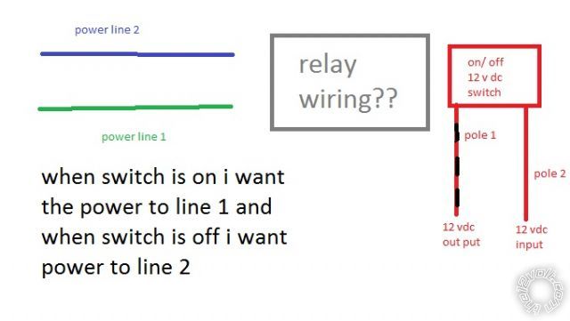
I'm only responding to the "switch on the #1 on & switch off #2 on" statement.
I'm ignoring ALL other text.
You have just described an SPDT relay. ie,
85 GND
86 switch output
30 common (ie, +12V supply, or line out)
87 line 1
87a line 2
thats all i needed to know thanks. i know i saw what looked like a farily easy diagram for the spdt in the relay section. i just didnt know which line would go where. i dont quite understand how relays work entirely, even after looking into the section on here for it.
A relay is just like a 2 position manual switch.
It can have a single pair of on-off contacts, or a set of change-over contacts, or any combination of contacts (multiple in & out etc).
As with a switch, the contacts have a rated current and a rated voltage. Excessive current may melt or
fuse or weld contacts. Excessive voltage may arc across contacts or arc to the case or screw or chassis etc.
The difference between a manual switch and a relay is that instead of your hand or fingers moving the switch contacts, an energised electromagnet (coil) moves the contacts (and usually a spring returns them when de-energised).
That coil requires a certain voltage - and hence a certain current - to guarantee
switching. Hence the coil's
rated voltage - eg, 12V.
In summary, instead of your muscles providing the force to switch, a coil aka electromagnet provides the force when sufficient voltage is applied.
Relays are actually quite simple - at least in basic operation.
But there are many types...
There are some great pictorials and animations on the net - not that I can find them LOL!
Maybe look at
bcae1 relays or
pcbheaven - How Relays Work.
FYI - I prefer to use "circuit" type diagrams for relays instead of using "physical" or wiring depictions. EG - figs 2 & 3 etc on
the12volt - relays as opposed to LH figs 1 & 4.
IMO that not only makes it clearer how the circuit works, but also that there is no predefined input or output per se - contacts are merely contacts. F.ex, relays that have labels like 30, 87 & 87a imply +12V in (30) with 87 & 87a as outputs. But 30 could be the output with (say) 87 from +12V and 87a from GND or not used.
awsome that first link pretty much broke everything down for me. for some reason i could understand the barney style in that much better. thanks alot guys. now on to the project