identifying 35 year old relay diodes
Printed From: the12volt.com
Forum Name: Relays
Forum Discription: Relay Diagrams, SPDT Relays, SPST Relays, DPDT Relays, Latching Relays, etc.
URL: https://www.the12volt.com/installbay/forum_posts.asp?tid=134495
Printed Date: May 13, 2026 at 10:09 PM
Topic: identifying 35 year old relay diodes
Posted By: toyotaguy
Subject: identifying 35 year old relay diodes
Date Posted: July 07, 2013 at 4:20 PM
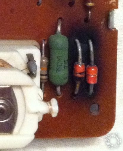
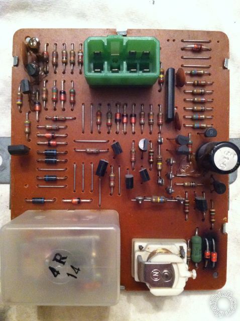
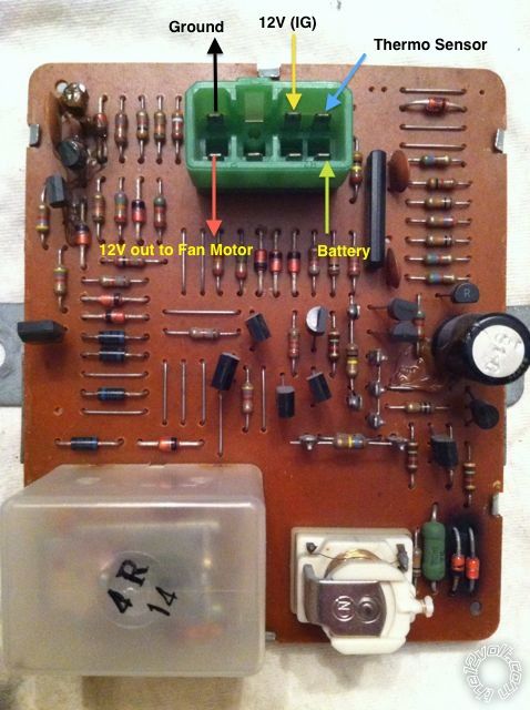
I have a "Cooling Fan Control Timer" (relay) from a 1978 Toyota FJ40 Land Cruiser that I'd love to repair than try and source a replacement for. The timer is pictured below with a closeup of the likely damaged components. My intro to EE class was in 1983 and my skills now consist of being able to use a multimeter. Any help would be greatly appreciated.
What I know: The module was made in Japan in 1978. It is from a 12V system and sits behind a 5A fuse. The only named component on the board is a cap with the "Nippon Chemi-Con" logo. The one burnt component appears to be a diode but the other - though appearing similar - has no marking to identify the cathode. Any idea what these two parts are and what I should purchase to replace them?
Replies:
Posted By: Ween
Date Posted: July 07, 2013 at 5:20 PM
hi,
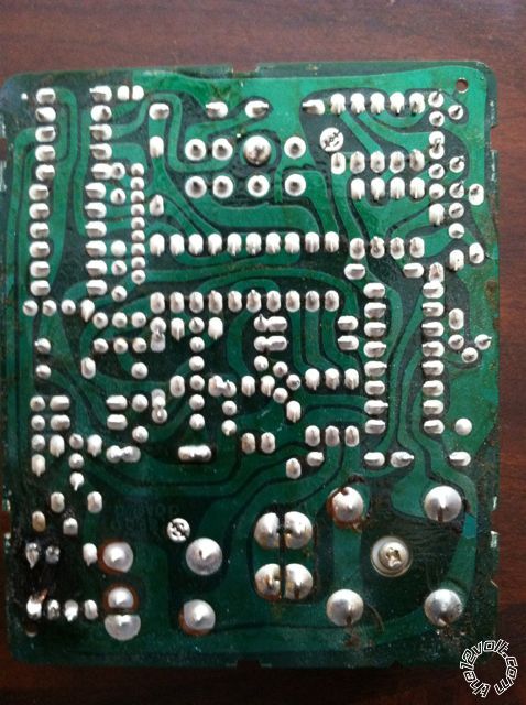
a circuit board (trace side) would help. i'm guessing the diode(s) are for suppression control for the relay coil near them. you'll probably need to carefully remove them from the board for testing and replacement. with the localized heating there, the pads may remove with additional heat from the soldering iron.
mark
Posted By: toyotaguy
Date Posted: July 07, 2013 at 6:09 PM
Ween] wrote:
hi,
a circuit board (trace side) would help. i'm guessing the diode(s) are for suppression control for the relay coil near them. you'll probably need to carefully remove them from the board for testing and replacement. with the localized heating there, the pads may remove with additional heat from the soldering iron.
mark
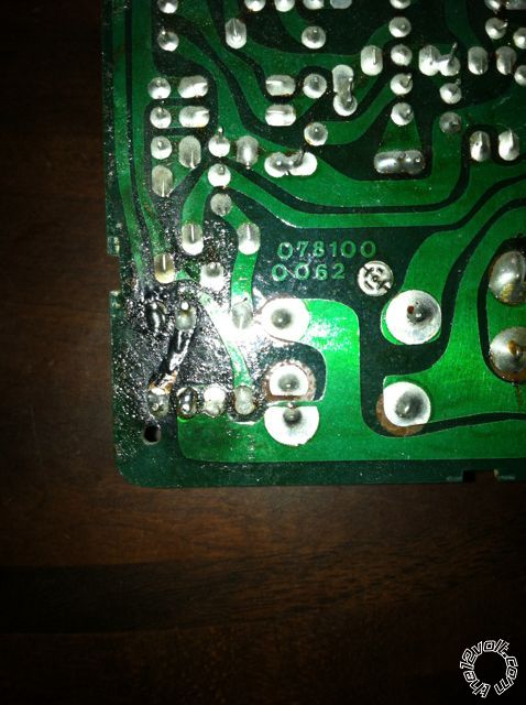
The two components were loose when I removed the board from its housing. The solder there fell off like loose grout. The trace on the back of the board has partially delaminated there also. Here are pics of the trace side.
Posted By: Ween
Date Posted: July 07, 2013 at 10:31 PM
did some searching and found wiring diagram for '78 fj40. can you id the wires at the connector? (which wire is at which position). there are only five shown; ignition, battery, ground, fan output, and sensor input. should help in determining use of the diodes.
Posted By: oldspark
Date Posted: July 07, 2013 at 11:42 PM
It's probably a Zener with series diode that some use for voltage clamping. Usually a reverse biased plain diode (IN4007 or 4007) diagonally across the 2 "end" pads will be okay especially since it's a transistor circuit.
What's the blackening on the diagonally opposite end of the PCB? (Condensation arc?)
Posted By: toyotaguy
Date Posted: July 08, 2013 at 8:03 AM
oldspark wrote:
It's probably a Zener with series diode that some use for voltage clamping. Usually a reverse biased plain diode (IN4007 or 4007) diagonally across the 2 "end" pads will be okay especially since it's a transistor circuit.
What's the blackening on the diagonally opposite end of the PCB? (Condensation arc?)
It's just shadowing from some brownish adhesive and my amateurish iPhone photographic skills. At first I thought a part or two had oozed its goo onto the board but all the fan controller boards have this goop on them.
Posted By: oldspark
Date Posted: July 08, 2013 at 9:42 AM
Ah - now it does look like gunk/glue etc. IMO it looked like similar blackish carbon etc. I can only assume that the12volt's image rendering has improved (ha ha).
Does my IN400x proposed repair make sense, and do you understand how?
Posted By: toyotaguy
Date Posted: July 08, 2013 at 6:13 PM
Ween] wrote:
did some searching and found wiring diagram for '78 fj40. can you id the wires at the connector? (which wire is at which position). there are only five shown; ignition, battery, ground, fan output, and sensor input. should help in determining use of the diodes.
Here are the connections from reading the wiring diagram and matching the wire color codes.
Posted By: Ween
Date Posted: July 08, 2013 at 6:23 PM
the two diodes appear to be in series on the ignition lead...polarity protection as well as a slight voltage drop. guessing the resistor adjacent provides some isolation for the timer circuitry from the relay coil operation.
Posted By: toyotaguy
Date Posted: July 08, 2013 at 8:52 PM
oldspark wrote:
Ah - now it does look like gunk/glue etc. IMO it looked like similar blackish carbon etc. I can only assume that the12volt's image rendering has improved (ha ha).
Does my IN400x proposed repair make sense, and do you understand how?
I'm afraid I don't quite follow and it's certainly not your fault. Are you saying I could replace the two diodes with a single IN400x?
Posted By: oldspark
Date Posted: July 09, 2013 at 12:47 AM
It may not be my fault, but I haven't decoded the circuit to sufficient detail - I'm being quick, or lazy.
I was assuming that those diodes were for relay-coil spike suppression, but if Ween thinks they are in series with IGN then that's an entirely different matter.
If it's an IGN voltage dropper or spike protector (to protect the circuit from IGN spike damage) then it would/could be the usual low Ohmage big Wattage resistor in series with a polarity protection diode (before or after the resistor) that then powers the circuit AND has a Zenor diode to GND to limit the voltage to some maximum (eg, 16V, or 10V, etc). But in that case there would be the power take-off from the junction of the 2 diodes, and the polarity protection diode would IMO be much larger than the apparent signal diode pictured - eg, ~100mA rated; ie - a bigger 1A 1N400x or larger would be used UNLESS the relay coils are powered direct from IGN +12V (since they'd probably take in excess of 100mA each).
However it could be 2 series diodes (Zenor & normal) to provide a fixed voltage drop from IGN +12V and hence no "junction" power take-off but IMO that is unlikely. Then again, I have seen many "strange" car electronics - even in Jap vehicles.
And maybe one relay is a polarity protection diode (ie, has a diode in series with its coil and its contacts connects the power).
But since I saw no track from the junction/common of the 2 diodes I assumed it was for coil spike protection.
IE - instead of the usual reverse connected IN400x etc diode across the relay coil (line end to +ve of the coil, other end to the coil's -ve or GND) which "shorts" -ve spikes to GND, a Zenor diode is added in series with the aforementioned diode but back-to-back (ie, line end to line end, else lines away from each other).
I fail to see the need for the added Zenor diode (why increase the -ve spike from ~0.7V to ~{ 0.7V plus the Zenor breakdown voltage } unless perhaps needing to limit noise or the current surge?) and hence my proposal to bypass (omit) it.
Of course in the time I wrote this reply I could probably have decoded enough of the circuit, but my printer has gone on vacation and I hate reverse engineering PCB circuits on screen. (Did I mention lazy - I mean, too busy?)
Posted By: toyotaguy
Date Posted: July 09, 2013 at 7:25 AM
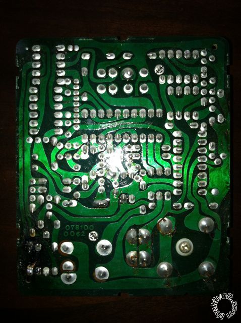
Here's another shot of the trace side without a flash, perhaps a little better. I also pasted a link to a post (scroll to post #170) containing the relevant pages from the 78 Toyota fan controller service specs.
I wish I were smarter about this. I started out at Ga Tech as a EE and after a particularly difficult class switched to IE. Since I went into the Navy after graduation I guess it ended up being somewhat irrelevant which engineering discipline I majored in. I'm now retired but this has really piqued my interest again. Maybe enough to take a community college class or something.
https://forum.ih8mud.com/40-55-series-tech/401196-fj40-carb-cooling-fan-do-you-run-yours-9.html
Posted By: oldspark
Date Posted: July 09, 2013 at 1:21 PM
It's 4:15Am here and I'm about to crash.
Those pages don't help - they don't show any circuitry. And you supplied the required connection info in your 2nd last pic.
But tomorrow tonight I'll see if I can su and root around with your pics assuming my girlfriend lets me off for the night (we'll be scavenging firewood for her).
Posted By: toyotaguy
Date Posted: July 10, 2013 at 7:10 AM
oldspark wrote:
It's 4:15Am here and I'm about to crash.
Those pages don't help - they don't show any circuitry. And you supplied the required connection info in your 2nd last pic.
But tomorrow tonight I'll see if I can su and root around with your pics assuming my girlfriend lets me off for the night (we'll be scavenging firewood for her).
Just trying to supply anything that might help. Thanks so much for your effort.
Posted By: oldspark
Date Posted: July 10, 2013 at 9:29 AM
YES! Time, or delays, or procrastination.
I've just been reminded of a weekend visit to a distant relative (my oops!), but I'll ensure SHE brings MY mobile router so maybe I can log in etc from there.
It's now 12:30AM Zulu and I have a full day tomorrow, and still no printer. So much for my Linux Mint 15 (xfce) install...
Posted By: toyotaguy
Date Posted: July 18, 2013 at 8:19 PM
Anyone else care to take a stab at this?
Posted By: toyotaguy
Date Posted: July 19, 2013 at 7:04 AM
Ween] wrote:
the two diodes appear to be in series on the ignition lead...polarity protection as well as a slight voltage drop. guessing the resistor adjacent provides some isolation for the timer circuitry from the relay coil operation.
Ween,
Can you suggest specific diodes to replace the two damaged ones with? I've been trying to sort this out for weeks and am about to throw in the towel. Thanks so much for your help.
Posted By: Ween
Date Posted: July 20, 2013 at 8:59 PM
did you think of looking on ebay perhaps for a spare for parts?
i think there are a few listed for around $20 shipped? then again 1N400* series diodes are like $1.50 for a pair at radio shack, or a multi-pack of 25 diodes for under $4. did some searching on fj forums for the operation of the timer module. from the description, it seems you could wire the unit on a test bench to check operation. if the diodes are inserted backwards on the ignition lead, the unit won't operate.
Posted By: toyotaguy
Date Posted: July 21, 2013 at 6:46 PM
Ween] wrote:
did you think of looking on ebay perhaps for a spare for parts?
i think there are a few listed for around $20 shipped? then again 1N400* series diodes are like $1.50 for a pair at radio shack, or a multi-pack of 25 diodes for under $4. did some searching on fj forums for the operation of the timer module. from the description, it seems you could wire the unit on a test bench to check operation. if the diodes are inserted backwards on the ignition lead, the unit won't operate.
The controllers I see listed now are for 79-80 and 81 models and I hadn't considered buying a similar one to rob components from. I'll try the 1N4001 diodes first. Thanks for your help.
|