durite 0 728 02 relay wiring
Printed From: the12volt.com
Forum Name: Relays
Forum Discription: Relay Diagrams, SPDT Relays, SPST Relays, DPDT Relays, Latching Relays, etc.
URL: https://www.the12volt.com/installbay/forum_posts.asp?tid=134568
Printed Date: May 13, 2026 at 5:12 PM
Topic: durite 0 728 02 relay wiring
Posted By: agemax
Subject: durite 0 728 02 relay wiring
Date Posted: July 19, 2013 at 8:13 AM
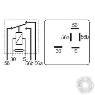
i have a Durite 0-728-02 latching relay and i am not sure which wires connect to which terminals on the relay.
the relay has 5 terminals, marked S,30,56,56a and 56b.
any help would be much appreciated thankyou
Replies:
Posted By: agemax
Date Posted: July 19, 2013 at 9:41 AM
here is a picture of the relay if this helps,
Posted By: agemax
Date Posted: July 19, 2013 at 10:10 AM
would 56a and 56b be 12v output, S being 12v pulse, 30 ground and 56 permanent 12v?
Posted By: agemax
Date Posted: July 19, 2013 at 11:18 AM
i have found the correct wiring for the relay on google.
thanks anyway 
Posted By: howie ll
Date Posted: July 19, 2013 at 2:27 PM
A) Not an latching relay.
B) It's a low beam high beam c/over relay.
-------------
Amateurs assume, don't test and have problems; pros test first. I am not a free install service.
Read the installation manual, do a search here or online for your vehicle wiring before posting.
Posted By: agemax
Date Posted: July 19, 2013 at 2:31 PM
it latches on with a 12v pulse, which is what i need
Posted By: oldspark
Date Posted: July 20, 2013 at 1:27 AM
I agree based on what I read - ie, each pulse toggles the relay contacts.
It's a mechanical latcher so it probably "remembers" (ie, stays in) the last position unlike 4017 based latchers (similar to what SAAB use) which can have a power-up reset to reset to low beam (which I like).
Posted By: agemax
Date Posted: July 20, 2013 at 5:19 AM
maybe i am using the incorrect terminology exactly but i wanted a relay that would toggle from one output to another with a 12v pulse (from a remote switched momentary relay).
i meant latching as it will "latch" from one output to another and stay there, rather than revert back once the 12v momentary pulse is absent.
i think i am making sense! 
Posted By: oldspark
Date Posted: July 20, 2013 at 7:17 AM
Oh you are definitely making sense. Maybe it is my terminology and expression that isn't!
What I last wrote was meant to say exactly as you just said (and before)...
Successive +12V pulses toggle or flip (flop) or swap the relay from one contact to another.
That's as you want, and as I understand the Durite 0-728-02 does.
My other ramble is incidental - ie, that being mechanical it stays in its last state, and it is commonly used as a low-high beam switcher.
Sorry if I confused. I just wanted to confirm your understanding, and draw Howard in case he knows something we don't (after all, if I say it's latching and Howard says it isn't latching, experience tells me I ain't right - though for once, I reckon I might be {yay! - or  ??}).
Posted By: howie ll
Date Posted: July 20, 2013 at 7:39 AM
I was wrong! It's a LATCHING relay although if our OP needs 10amps or less I would strongly recommend an Omron or Panasonic for about a quarter of the cost.
-------------
Amateurs assume, don't test and have problems; pros test first. I am not a free install service.
Read the installation manual, do a search here or online for your vehicle wiring before posting.
Posted By: agemax
Date Posted: July 20, 2013 at 7:48 AM
howie ll wrote:
I was wrong! It's a LATCHING relay although if our OP needs 10amps or less I would strongly recommend an Omron or Panasonic for about a quarter of the cost.
thanks for the reply, it is powering a motorcycle and the main fuse is 15amp so i think this relay is ok for the job.
Posted By: agemax
Date Posted: July 20, 2013 at 8:17 AM
i seem to have run into a problem.
i have wired 30 and 56 to 12v permanent supply.
i get 12v out on 56b and not 56a
the 12v momentary input is connected to S on the relay and gets 12v when the remote button is pressed.
but.......... it wont switch from 56b to 56a. any ideas where i may have gone wrong?
the momentary relay that outputs the 12v to the S is grounded but there is no ground on the Durite relay, is this the problem?
thanks in advance
Posted By: oldspark
Date Posted: July 20, 2013 at 8:33 AM
30 & S must go to opposite polarities, ie if 30 is GND, then S is a 12V pulse. (Either can be pulsed.)
Posted By: howie ll
Date Posted: July 20, 2013 at 8:35 AM
56 in an "off state is N/C to 56a, actuating the coil via 30 will connect 56 to 56b and disconnect it from 56a.
-------------
Amateurs assume, don't test and have problems; pros test first. I am not a free install service.
Read the installation manual, do a search here or online for your vehicle wiring before posting.
Posted By: agemax
Date Posted: July 20, 2013 at 8:56 AM
wow, thanks guys, it works properly now.
just one more question......
i only have a 12v output connected to 56b. when the relay is switched by the 12v pulse, 56b becomes live (as i want it to) and there is 0v on 56a, as it should be.
when i switch it again, the 12v drops off 56b (as it should do) and i am still getting 0v on 56a.
is this correct and safe to use? will there only be a 12v output on 56a if there is something connected to it? eg, a light bulb, + to 56a and - to ground?
thanks.
Posted By: agemax
Date Posted: July 20, 2013 at 9:17 AM
oh,hang on a minute i got my a's and b's all mixed up.
there is a 12v output connected to 56A. when the relay is switched by 12v pulse 56A becomes live. and 0v on 56B.
when switched again, 56A drops off but there is still 0v on 56B.
sorry again for any confusion
Posted By: agemax
Date Posted: July 20, 2013 at 3:20 PM
hmmm, i have just studied the diagram on the side of the relay, (shown in earlier post) and it seems when the power is switched to 56b the ground wire from 30 moves away as well, so that is why there is no 12v output from 56b...... 
now i am confused because i thought being a changeover relay it is supposed to swap the output voltage from 1 output to the other?
should this be the case or am i completely on the wrong track?(again)
Posted By: oldspark
Date Posted: July 20, 2013 at 6:46 PM
Well I have certainly been wrong. I read that it was a mechanically latching relay, but further reading suggests it's a wired latcher - ie, it latches thru internal switching. Hence it has no memory, and it draws power when latched on (ie, 56 connected to 56a).
Furthermore it seems that S must be a -ve (GND) pulse, not +12V, and that when on, 56a is connected to 30.
Hence 30 must be +12V. (And bad luck if 56 is unpowered so that the coil's +12V 30 powers the load - ie, ensure 30 is appropriately fused and wired.)
Only this morning I said how I %$^%#@!! hate specialised relays like this. I prefer (non-relay) circuits that drive standard relays.
Unless this application requires zero coil current once latched, IMO this is a classic T-type flip flop or even 4017 application.
Posted By: agemax
Date Posted: July 20, 2013 at 7:02 PM
oldspark wrote:
Well I have certainly been wrong. I read that it was a mechanically latching relay, but further reading suggests it's a wired latcher - ie, it latches thru internal switching. Hence it has no memory, and it draws power when latched on (ie, 56 connected to 56a).
Furthermore it seems that S must be a -ve (GND) pulse, not +12V, and that when on, 56a is connected to 30.
Hence 30 must be +12V. (And bad luck if 56 is unpowered so that the coil's +12V 30 powers the load - ie, ensure 30 is appropriately fused and wired.)
Only this morning I said how I %$^%#@!! hate specialised relays like this. I prefer (non-relay) circuits that drive standard relays.
Unless this application requires zero coil current once latched, IMO this is a classic T-type flip flop or even 4017 application.
ok, now i am totally and completely lost! i have 30 as a permanent ground and "S" as a pulse +12v and it appears to work ok, except i get no 12v output from 56b when it is switched.
56 is a fused 12v permanent supply.........
Posted By: oldspark
Date Posted: July 20, 2013 at 7:22 PM
I suggest you contact Durite.
The only meaningful info I have is...

...from QRZ Forum's Needing help figuring out a latching relay though that's for a VW 111-941-583 and may differ from the Durite 0-728-02
Posted By: agemax
Date Posted: July 20, 2013 at 7:39 PM
oldspark wrote:
I suggest you contact Durite.
The only meaningful info I have is...
...from QRZ Forum's Needing help figuring out a latching relay though that's for a VW 111-941-583 and may differ from the Durite 0-728-02
that is the same picture i have on the side of the relay i have. although it was advertised with the picture i posted earlier in the thread. the 2 outputs 56a and 56b look different. i have a feeling they sent me the wrong relay 
Posted By: Ween
Date Posted: July 20, 2013 at 8:01 PM
that's a vw dimmer relay with flash-to-pass function. the secondary contact from 30 to 56a completes that circuit. look for VW 411941583C,
the letter suffix determines whether the F-T-P exists in the relay.
and of course per DIN wiring standards, term 30 is battery power.
looking at the 583C relay as this is typed.
Posted By: howie ll
Date Posted: July 21, 2013 at 2:18 AM
So can I take back my previous apologies and refer you all back to my first post?
-------------
Amateurs assume, don't test and have problems; pros test first. I am not a free install service.
Read the installation manual, do a search here or online for your vehicle wiring before posting.
Posted By: agemax
Date Posted: July 21, 2013 at 2:36 AM
i really dont know?
if the contacts in the relay were arranged as in the schematic i posted in post #3 then i think there would not be a problem.
as i have a relay which the contacts are arranged as in the picture posted by oldspark, then i am guessing they have sent me the wrong relay as i cannot see how these contacts work to get power to 56b.
they advertised it as the relay with the contacts shown in post #3 so i guess i will have to contact them Monday and get them to send me the correct relay.
i would post a link to the e**y listing but i dont think i am allowed to...
Posted By: oldspark
Date Posted: July 21, 2013 at 3:26 AM
The problem with the post #3 diagram is that it says nothing about how the relay latches.
I'd also argue that the diagram I posted is not incompatible with post #3's pic though it still doesn't explain how it latches.
Adding an SPDT (86 to 56b) achieves what you want.
Posted By: agemax
Date Posted: July 21, 2013 at 4:11 AM
as it is wired now, it works perfectly, except there is no output on 56b when it is switched to that side.
when 56a is latched on 56 and 30 connect making the circuit, but when 56b is latched, it gets the 12v from 56 but not the ground from 30.
i can still use it as it is, as it does what i want, switches 56b on or off with a 12v pulse. therefore turning the ignition on and off.
the original idea for using this relay was that when 56a is switched off (cutting power to the bike) it would then power an alarm from the other contact 56b.
i can live with it as i will just have to wire in a power source to supply the alarm when the bike ignition is off.
i wanted to use the relay as it would be minimum fuss and a tidy install, without to many relays and wires.
Posted By: howie ll
Date Posted: July 21, 2013 at 4:23 AM
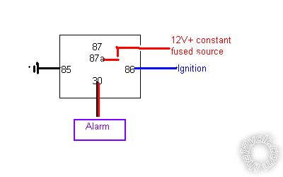
Bleeding heck just use this:-
auto_switch.bmp
Standard 5 pin Bosch/Tycho cube relay around £5 ------------- Amateurs assume, don't test and have problems; pros test first. I am not a free install service.
Read the installation manual, do a search here or online for your vehicle wiring before posting.
Posted By: agemax
Date Posted: July 21, 2013 at 4:28 AM
howie ll wrote:
Bleeding heck just use this:-
auto_switch.bmp
Standard 5 pin Bosch/Tycho cube relay around £5
yeah, i could do but it defeats the object of what i want.
i will just wait until tomorrow and contact the seller and get them to send me the correct relay.
thanks anyway for your help
Posted By: howie ll
Date Posted: July 21, 2013 at 4:31 AM
Sorry, very confused, I thought you simply wanted to turn the alarm on and off automatically, wth are you trying to achieve?
-------------
Amateurs assume, don't test and have problems; pros test first. I am not a free install service.
Read the installation manual, do a search here or online for your vehicle wiring before posting.
Posted By: agemax
Date Posted: July 21, 2013 at 4:41 AM
ok, i will explain from the start.
i have a remote control unit to power the ignition and starter on my motorcycle. the remote relays are momentary action so i need a latching relay that is activated by a 12v pulse to turn the ignition on, so it is on all the time until i pulse it again to turn the ignition off again. (same principal as using a key switch)
when i switch the ignition off, i want the 12 to redirect (through the changeover relay) to power the alarm.
then, when the ignition is turned on again it diverts the power away from the alarm to the ignition circuit.
does that sort of make sense now?
Posted By: howie ll
Date Posted: July 21, 2013 at 5:26 AM
Any idea what your ignition draws in the way of amperage?
Alternatively, a timer device, search for Raw power might do it.
Or even an existing R/S security device such as a Viper unit.
-------------
Amateurs assume, don't test and have problems; pros test first. I am not a free install service.
Read the installation manual, do a search here or online for your vehicle wiring before posting.
Posted By: agemax
Date Posted: July 21, 2013 at 5:36 AM
the ignition circuit draws no more than 15amps.
i dont see how a timer could be used?
Posted By: howie ll
Date Posted: July 21, 2013 at 5:44 AM
We're running around in circles here, the Viper 5204 is officially available in the UK, set to passive arming it will do all you need.
-------------
Amateurs assume, don't test and have problems; pros test first. I am not a free install service.
Read the installation manual, do a search here or online for your vehicle wiring before posting.
Posted By: agemax
Date Posted: July 21, 2013 at 5:59 AM
you are right, but it is far too expensive, designed for a car, not a motorcycle and the point of my exercise is to build my own system, not just buy one off the shelf.
if that was my goal i would not have bothered posting on this site.
i thought the whole idea of this site was to help out the DIY enthusiast, not to direct them to an off the shelf item.
thankyou for all your help so far, i will persevere and complete this project myself.
i will post up any further information in my other motorcycle thread. 
Posted By: howie ll
Date Posted: July 21, 2013 at 7:02 AM
Let me assure you that your journey has been started many times and you will probably realise what a waste of your time and money it's going to be.
You will have no safeties.
A modern R/S + alarm is about the size of two ciggie packets, easy enough to conceal in a dry storage section.
-------------
Amateurs assume, don't test and have problems; pros test first. I am not a free install service.
Read the installation manual, do a search here or online for your vehicle wiring before posting.
Posted By: oldspark
Date Posted: July 21, 2013 at 7:33 AM
Yeah - center stand, neutral, timed off...
PICAXE 08M2.
Posted By: agemax
Date Posted: July 21, 2013 at 7:37 AM
oldspark wrote:
Yeah - center stand, neutral, timed off...
PICAXE 08M2.
i have no centre stand, only a kick stand. the starter solenoid is grounded through the neutral light switch, so if the bike is not in neutral, the starter wont operate.
why would it need to be timed off????
Posted By: agemax
Date Posted: July 21, 2013 at 7:43 AM
howie ll wrote:
Let me assure you that your journey has been started many times and you will probably realise what a waste of your time and money it's going to be.
You will have no safeties.
A modern R/S + alarm is about the size of two ciggie packets, easy enough to conceal in a dry storage section.
the remote system i am using is the same size as 1 cig packet, with a relay hidden elsewhere.
it is not a waste of time and money. if they had sent me the correct relay in the first place it would be working and finished by now.
when i resolve this with the seller and they send me the right relay all will be good, and all working as i want it to for less than £50GBP
Posted By: howie ll
Date Posted: July 21, 2013 at 7:45 AM
Good luck etc. but are there any failsafes?
-------------
Amateurs assume, don't test and have problems; pros test first. I am not a free install service.
Read the installation manual, do a search here or online for your vehicle wiring before posting.
Posted By: agemax
Date Posted: July 25, 2013 at 11:28 AM
i have been away for a week but now i am back i have been in touch with Durite and now have the correct wiring for the relay.
30 is permanent battery negative.
56 is permanent battery positive.
S is the switched 12v pulse from my R/C unit.
56a is permanent 12v output.
56b is switched 12v(latched) output.
so the ignition circuit is wired to 56b
i have not yet decided whether to use the permanent 12v from 56a yet or just blank it off for now with a "dummy" spade terminal
Posted By: howie ll
Date Posted: July 25, 2013 at 12:55 PM
What worries me is that by ISO convention, 30 is constant POS, 31 would be constant NEG.
-------------
Amateurs assume, don't test and have problems; pros test first. I am not a free install service.
Read the installation manual, do a search here or online for your vehicle wiring before posting.
Posted By: agemax
Date Posted: July 25, 2013 at 12:59 PM
howie ll wrote:
What worries me is that by ISO convention, 30 is constant POS, 31 would be constant NEG.
there is no 31 on the relay.
Posted By: howie ll
Date Posted: July 25, 2013 at 1:12 PM
Yes but what they told you is correct accept as a reputable company they should have labelled it 31, then I can assure you we wouldn't have had to go 5 pages on this, just as I rightly said 56 refers to lighting, 30 and 31 are the pin IDs for POS and NEG.
-------------
Amateurs assume, don't test and have problems; pros test first. I am not a free install service.
Read the installation manual, do a search here or online for your vehicle wiring before posting.
Posted By: agemax
Date Posted: July 25, 2013 at 1:30 PM
howie ll wrote:
Yes but what they told you is correct accept as a reputable company they should have labelled it 31, then I can assure you we wouldn't have had to go 5 pages on this, just as I rightly said 56 refers to lighting, 30 and 31 are the pin IDs for POS and NEG.
what should be labelled 31? 56?
it has carried on this far because you either contradict yourself or do do not give explanatory answers! explain WHAT should have been labelled 31
Posted By: howie ll
Date Posted: July 25, 2013 at 2:50 PM
Sorry, 30 should have been labeled as 31 but if it works as advertised that's fine.
-------------
Amateurs assume, don't test and have problems; pros test first. I am not a free install service.
Read the installation manual, do a search here or online for your vehicle wiring before posting.
|