getting power to my trailer brake lights
Printed From: the12volt.com
Forum Name: Relays
Forum Discription: Relay Diagrams, SPDT Relays, SPST Relays, DPDT Relays, Latching Relays, etc.
URL: https://www.the12volt.com/installbay/forum_posts.asp?tid=134977
Printed Date: April 05, 2026 at 12:14 PM
Topic: getting power to my trailer brake lights
Posted By: ecadee
Subject: getting power to my trailer brake lights
Date Posted: September 30, 2013 at 5:17 PM
I have a 6 pole square trailer wiring connector that is not compatible with the trailer wiring. The connector has a separate pole for RT, LT, GND, Running Lights, Brake lights, and AUX,. The trailer is conventionally wired with Yel/Brn to run the left turn, left brake, and left running lights, Grn/Brn to do the same for the right side, getting their power from the conventional flat 4 or flat 5 connectors. The problem is that the 6 pole connector has a pole (red wire) that is dedicated to the brake light only (e.g. when I apply the brakes, only the red wired pole is hot).
Is there a way, using relays, to "tap' into the Yel/Brn (left turn/running/brake lights) wiring and the Grn/Brn (right turn/running/brake lights) wiring with the red powered brake light wire lead so that when the brakes are applied, power to both the left side and right side wiring is cut off and the red brake light lead would now supply power to both sides turn/running/brake lights? And, of course, when the brake is released the red wire lead goes cold and the Yel/Brn and Grn/Brn wires become hot again.
I'm stumped on how to do this and am looking for brighter electrical minds who can also draw diagrams. ;-)
TIA.
-------------
You are what you do.
Replies:
Posted By: oldspark
Date Posted: October 01, 2013 at 12:07 AM
Diodes - big enough to handle the brake bulb current.
Else 1N400x diodes from each (YelBrn etc) to individual SPST relays 86; 30 to stop bulbs & each 87 to respective source (Yel/Brn) (and 85 to GND).
Hence stop is on if either "side" is on.
At first I read it as if you wanted a brake/flasher separator, but my reread may not have considered all issues (like flashing R & L signals).
Usually the solution is to rewire the trailer lights to suit the vehicle.
Posted By: davep.
Date Posted: October 02, 2013 at 3:48 PM
The easy solution is to add two more lights on the trailer with the 'big' filaments wired to the brake lights (red) in an added 6-pole connector that matches the subject tow-car. If the trailer is used with other tow cars with the conventional "flat-4" connector, leave both connectors on the trailer. When trailer is used with a flat-4 towcar, the outer lights will have 3 functions (brake, turn, tail) the inners only tail. When used with the 6-pole, outers will be turn/tail, and the inners brake/tail.
```````````````````````````````````````
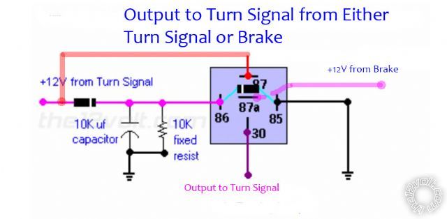
It can also be done with two relays. One for each side. use this diagram to create a pulsing output to steady with the following changes:
#30 = Output to trailer light yel or green
#87a = Brake input (red on tow car)
#87 = Turn sig input PRIOR to the resistor/capacitor network for the relay coil.
The circuit will work like this:
At rest, with no turn sig input, the brake signal will be connected to trailer through the N.C. 87a contacts.
When turn sig is present, the first pulse energizes the relay coil connecting the trailer to 87 which is hot when the signal is blinked 'on'. When signal blinks off, relay will stay in 'signal position', but the trailer light will go off because there is no voltage present at 87 when turn signal is blinked 'off'.
About 3 seconds after last turn signal pulse, the relay coil will de-energize returning that side to brake function.
I used this circuit on a project where I utilized the bright amber front turn signals as Daytime Running Lights. I got the idea from watching on-coming Freightliner trucks on the Interstate. Those use the turn signals as DRL's. One side stays bright, the other blinks the signal. When the signals stop, about 3 seconds later, it comes back on solid. It would do the same for your trailer application.
Posted By: ecadee
Date Posted: October 02, 2013 at 6:30 PM
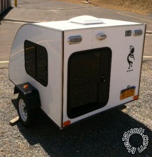
Thanks for getting back to me. My trailer is a small camper that I pull behind both my car and motorcycle. Both tow vehicles have 6pole square connectors. I have another small cargo trailer configured the same with the 6 pole.
I don't believe rewiring the trailer to fit the 6pole would work because there is only one set of tail lights. All of my prior (and current) trailers have come from the factory with two sets of rear lights (a usual occurrence for small motorcycle trailers) and a 6pole connector. So, in order for me to keep commonality with my tow vehicle connectors I have to have a second set of lights installed... unless I can somehow figure out how to use relays to accomplish with two dual filament lights when I would normally have four to work with.
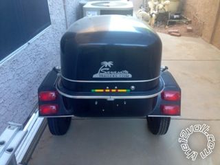
Factory installed dual set of lights
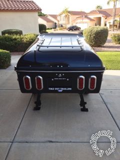
Factory installed dual set of lights
The two lights at the top are the ones I need to work with. ------------- You are what you do.
Posted By: ecadee
Date Posted: October 02, 2013 at 6:47 PM
davep.
Your description of the relays sounds like what I'm looking for.
I'll let you know how it works.
Thanks!
-------------
You are what you do.
Posted By: ecadee
Date Posted: October 03, 2013 at 7:57 PM
davep
I just want to make sure of what I think I know.
Does this look right to you?
Do I need a fuse in line with the brake wire? If so, how big?
What are the black with white stripe rectangles? ------------- You are what you do.
Posted By: davep.
Date Posted: October 03, 2013 at 11:32 PM
That looks good. Exactly what I had in mind.
The "black rectangles with a stripe" are 1 amp diodes. They are one-way valves for electricity. Current flows in the direction of the band towards negative. You can get a pack of 5 at radio shack for a few bucks. When you find a store that has the capacitors, they will surely have 1A Diodes too.
You must use the diode on the input to the Resistor/Capacitor network for the coil, so the R/C network doesn't flow back into the circuit when the signals blink off.
The diode across the relay coils is for "anti-spike". I am not certain why the author of this diagram included it in this circuit. But it won't hurt anything, so put one there too.
The brake light circuit should be fuse protected somewhere in the towcar, so an additional fuse is not necessary for circuit protection. If you add a fuse at say the trailer connector, or the brake input to the relays, then a short in the trailer lights would blow the new fuse, and the tow car brake light would remain functional. For this to work, the new fuse has to be smaller than the tow car brake fuse.
Personally, I'd trust my wiring, and the towcar's existing protection. Familiarize yourself with where the fuses for the trailer lighting are. Particularly on a road bike like a Harley.(If that's what you have). Learn where the fuses are at your convenience, not when you're in a hurry to find a blown one and can't get the seat off.
Thanks for the follow-up.
|