type of relay or suggestions
Printed From: the12volt.com
Forum Name: Relays
Forum Discription: Relay Diagrams, SPDT Relays, SPST Relays, DPDT Relays, Latching Relays, etc.
URL: https://www.the12volt.com/installbay/forum_posts.asp?tid=136139
Printed Date: March 29, 2026 at 10:11 AM
Topic: type of relay or suggestions
Posted By: webpager
Subject: type of relay or suggestions
Date Posted: February 23, 2014 at 7:49 PM
I had always heard of what I am about to describe as a drop relay, but I was informed recently otherwise. Now, I need to buy/build one and am not sure of what to call it.
Relay - normally open. Closed via Momentary. When power is interrupted, ie the car is turned off, the relay opens again. I want to add switches for a few items (a USB block to charge stuff, radar detector, inverter, more). I don't want it on as I start the car. So once I start it, I can hit the momentary switches, the relay(s) is(are) activated, and I have powered items. I turn off the car and these items go off and stay off until I restart AND hit the momentary again.
Suggestions? Names? Electromechanical or SSR?
TIA from a newbie to these forums.
-------------
Webpager - Upfitter, computer guy, car guy. I can't tell the difference between Columbian or African coffee, but I knew at age 4 the difference between volts, watts and ohms.
Replies:
Posted By: KPierson
Date Posted: February 23, 2014 at 10:45 PM
Use a standard 30A Bosch style automotive relay. Connect the momentary switch between the (+) side of the coil and an accessory wire in the vehicle. Accessory wires are powered in the "ON" key position but not the "crank" key position.
You will then need to latch the (+) output of the relay back to the (+) coil to make it stay on after you push and release the button
Pin 85 - ground
Pin 86 - (+) coil, connect to accessory feed through momentary switch, also connect to pin 30
Pin 87 - Fused 12vdc source
Pin 30 - 12vdc output, also connect to pin 86
-------------
Kevin Pierson
Posted By: webpager
Date Posted: February 24, 2014 at 1:08 PM
Thank you Kevin. For some reason I had thought it was a different relay. This makes perfect sense. I appeciate you breaking it down to the specific pins.
-------------
Webpager - Upfitter, computer guy, car guy. I can't tell the difference between Columbian or African coffee, but I knew at age 4 the difference between volts, watts and ohms.
Posted By: webpager
Date Posted: February 24, 2014 at 6:45 PM
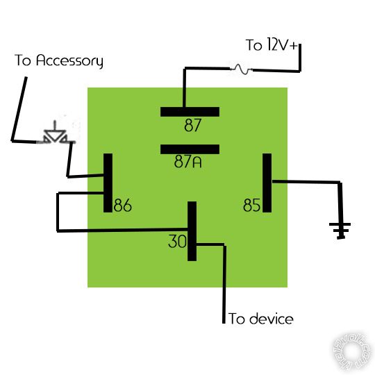
To be sure, this is what you described Kevin. Is this correct? ------------- Webpager - Upfitter, computer guy, car guy. I can't tell the difference between Columbian or African coffee, but I knew at age 4 the difference between volts, watts and ohms.
Posted By: the12volt
Date Posted: February 24, 2014 at 7:12 PM
Yes, that will work, but make sure terminal 87 is going to an accessory 12V+ source and not a constant 12V+ source, otherwise it will not turn off with the key. -------------  the12volt Support the12volt.com the12volt Support the12volt.com
Posted By: webpager
Date Posted: March 15, 2014 at 1:37 AM
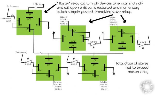
OK - been working on this one. Any expertise is appreciate. What do you think? I figure that instead of the Bosch style auto relays I'll see if I can find electronic ones. But either way, here's what I hope to do with it. I would also run a common ground (not shown on the graphic).
Thoughts? Comments? Suggestions?
 ------------- Webpager - Upfitter, computer guy, car guy. I can't tell the difference between Columbian or African coffee, but I knew at age 4 the difference between volts, watts and ohms.
Posted By: oldspark
Date Posted: March 15, 2014 at 2:06 AM
I'd forget electronic relays. If space is a premium, used the micro-DIN relays.
Posted By: harryharris
Date Posted: March 15, 2014 at 8:11 AM
The micro DINS are smaller than PCB standard pin relays.
-------------
Test before boxing up.
Posted By: oldspark
Date Posted: March 15, 2014 at 10:26 AM
Yeah - a micro is about half the volume of the mini - 22.5mm x 15mm x 25mmH + 11mm spade protrusion noting that the coil spades (86 & 85 = 1 & 2) and NO spade (87a = 4) are 4.8mm whereas 30 & 87 = 3 & 5 are normal 6.3mm.
2 micros side by side are a bit wider than a mini.
And mechanical relays are more reliable than solid state.
webpager - one consideration with your wiring is that until the relay actuates and closes 30 to 87, the switch will supply the load current.
If that's an issue, a diode can be inserted between 87 & 86; line end towards 86. Hence when actuated, 87 supplies +12V thru the diode to 86 to keep the relay energised, but the switch +12V to 86 cannot flow thru the diode to 87 and hence the load. Any 1N400x diode will do, but if buying diodes, get 1N4004 else 1N4007 as they can be used for spike prevention - ie, across the coil 86 to 85 with the line end towards the more +ve (namely 86 by convention and as per your diagram). Spike suppression diodes are used when electronics control the relay coil or if spikes are undesirable to minimise system noise (voltage transients).
Posted By: webpager
Date Posted: March 15, 2014 at 11:57 PM
I notice I saved the graphic with an extra connection in each relay - power going back from 30 to 86. Didn't mean for that - I thought I unchecked those layers when creating the graphic.
They were from the original relay with momentary and drop when power removed relay.
-------------
Webpager - Upfitter, computer guy, car guy. I can't tell the difference between Columbian or African coffee, but I knew at age 4 the difference between volts, watts and ohms.
Posted By: steve392
Date Posted: March 20, 2014 at 7:05 AM
I'm still new to this forum and am certainly learning a lot and reading as many posts as I can, so I hope you don't mind me asking a question regarding the above schematic....Oldspark mentioned that a diode can be inserted between 87 and 86 to energize the coil. I'm not sure if that was at the "master" relay or at each of the "slaves", but wouldn't that negate the switch (either momentary or s.p.s.t.)? It seems to me that once 87 is energized, either by the car being started and running in the case of the master relay, or by the master relay energizing the slave relays, the diode between 87 and 86 bypasses the switch entirely? Maybe another way to put it is if there is a diode between 87 and 86, what does the switch do?
I'm probably missing the logic somewhere, please clarify.
Thanks,
Steve
-------------
Posted By: oldspark
Date Posted: March 20, 2014 at 8:30 AM
No problems asking - that's how you learn. (Assuming the reply is understandable.)
And no problems seeking extra clarification or assurance - that helps ensure no misunderstandings or mistakes occur. Often a restatement of the question or intent - or a paraphrasing of the answer(s) - eliminates errors (ie, misinterpretation or misapplication).
But your assessment is correct.
My comment re the diode was because I interpreted your " Relay - normally open. Closed via Momentary. When power is interrupted, ie the car is turned off, the relay opens again as meaning a latching relay. IE - a momentary on turns on the relay and it stays on - despite the momentary being off - until the 'master' power (IGN) is turned off.
Your first diagram IMO showed a momentary push button and I assumed your 2nd diagram with SPST switches was merely a simpler symbol.
And I may also have confused this with another thread I was involved in - not that I can find it now (either here on the12volt else mp3car.com).
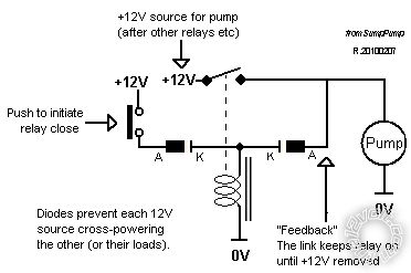
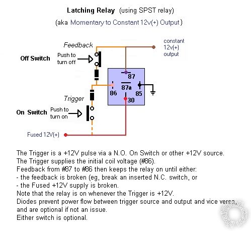
Anyhow, below is the circuit diagram of what I was referring to, and below that is its equivalent wiring diagram but with a manual turn-off normally closed push button (ie, so enable turn off without removing the "master" power).
Hopefully the descriptions explain the diodes - ie, so the momentary on, or normally closed off, switches do not carry the load current whilst the relay contacts are still closing. [ FYI - I took both diagrams from the 2010 the2volt thread " capacitor value for latching relay?". The wiring diagram circuit was used as a tank fill or sump drain circuit whereas the upper circuit diagram was used for some manual-push turn on that stayed on until the main/master +12V was removed (eg, IGN off). ]
Posted By: webpager
Date Posted: March 20, 2014 at 2:56 PM
Hey Oldspark,
Seems another person involved with the thread. I had put up the original question and some replies.
What I had envisioned is this: the "master" relay, using a momentary switch, would shut down with the car and be open until manually closed with the switch. When closed, it would send power to the other relays, or "slaves." Those would have any type of switch, SPST, SPDT, MOM, etc. The master is just to stop something from starting accidentally when I restart the car and to prevent spikes to whatever is connected. So far I plan to have lights, a scanner, power inverter, a USB block for charging devices, a Bluetooth adapter, and an air horn attached via the relays. The inverter may be on its own "master" momentary - I need to check the amperage.
What I forgot when I put up the graphic of the 5 relays was to delete the jumper from 30 to 86 on the 4 "slave" relays.
-------------
Webpager - Upfitter, computer guy, car guy. I can't tell the difference between Columbian or African coffee, but I knew at age 4 the difference between volts, watts and ohms.
Posted By: webpager
Date Posted: March 20, 2014 at 11:10 PM
Corrected the graphic
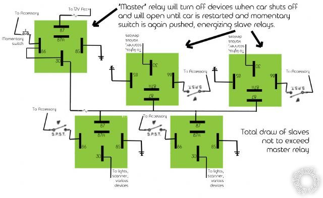
Removed the jumper, noted that the switches get power from accessory ------------- Webpager - Upfitter, computer guy, car guy. I can't tell the difference between Columbian or African coffee, but I knew at age 4 the difference between volts, watts and ohms.
Posted By: oldspark
Date Posted: March 21, 2014 at 1:35 AM
Sorry webpager - I did confuse posters. Alas my old habits are returning - I'm not reading WHO posts, merely the post content. (That's something that is not too bad on the12volt, but on other sites I have learned to ignore the in-butters. IMO if they want to tackle me, they should open a new thread.)
Of course I could blame Steve for butting in (LOL), but no - IMO his question was quite acceptable and not (yet) a hijack. However that is up to the OP (you, webpager) to decide.
Maybe it does show why some prefer a new thread to be opened by new posters or for related questions. The new thread can refer back or include a link to the original, and the original could have " (rather than hijack or complicate this...) See my new thread ABC" etc.
Ah - so many new names and members. Steve and HarryH are even newer than you. OldFarts like me get so confused. (Get? I am always confused!  )
Anyways, your diagram looks fine by me.
You can turn on any slave but they will not turn on until you manually momentarily push the "Master" momentary switch.
ACC must be on for the Master to come on.
The Master relay stays on/energised until ACC loses power.
When the Master turns off, all power is lost to the slave devices/relays.
Be aware that ACC drops when cranking. (But...)
All slaves with SPST switches turned on will turn on again once the Master is re-energised - eg, another manual push after cranking.
Oh no, stupid me. I wrote the following and then realised it's wrong because of the latching aspect - you have to turn OFF the Master Relay's power (#87) to drop it and hence slave relays/loads.
However adding a manual off as per 2nd (circuit) diagram could overcome that.
Also be aware that the Master Relay's power can be direct from battery +12V. Only the Master momentary switch need be powered from an ACC circuit. The advantage is that your slave loads do NOT load the ACC circuit, and the slaves get the 'cleanest' +12V power - ie, direct from the battery (via a fuse of course). The latter is often preferred by audio buffs, maybe PCs, or those with noisy loads (inverters etc).
Ah yes, we "experts" never make mistakes do we? (Readers - please ALWAYS be wary!)
At least that saves me the no drop during cranking solution...
BTW - I looked up "drop relay" and found " Relay activated by incoming ringing current to call an operator's attention to a subscriber's line." (from The Free Dictionary (by Farlex).
Man, that's so pre-1930's!
FYI - for those that think only "experts" achieve etc, the automated telephone switch (exchange) was invented by a Funeral Director. It's yet another of many " as if other's can't have valid input" examples.
Posted By: webpager
Date Posted: March 21, 2014 at 6:51 PM
I don't consider it hijacking. Steve392 was asking about the circuit I showed and you commented on. I figure he was asking an on topic question.
Thanks for your input, info and advice. I think I'm going to do this with 2 boxes: 1 small one for switches in the passenger compartment, and 1 large one for relays that will be under the hood. Ugghh - an inverter, a GPS (doing what I can to hide the GPS since it's a 7" unit but figure it'll still be heard), an electronic air horn, a USB charging block, a set of driving lights, and possibly 2 more to activate front or rear cameras. If I add a switch for the rear (not sure I would since it would come on with the vehicle in reverse), I know I'd need to add a diode between the back up light and the camera to prevent the back up lights from energizing. But I figure a forward facing camera for parking as well (I really like this vehicle).
-------------
Webpager - Upfitter, computer guy, car guy. I can't tell the difference between Columbian or African coffee, but I knew at age 4 the difference between volts, watts and ohms.
|