parklights and turn signals as one.
Printed From: the12volt.com
Forum Name: Relays
Forum Discription: Relay Diagrams, SPDT Relays, SPST Relays, DPDT Relays, Latching Relays, etc.
URL: https://www.the12volt.com/installbay/forum_posts.asp?tid=136284
Printed Date: March 22, 2026 at 4:48 PM
Topic: parklights and turn signals as one.
Posted By: themartindobson
Subject: parklights and turn signals as one.
Date Posted: March 16, 2014 at 5:47 PM
Hey Guys, my father-in-law has an older project car that he has built for the ground up and has asked me to do the wiring. 12v system.
Now, he has chosen to use two LEDs on the front wheel ferrings for usage of a park light and turn signal purpose. One LED per side of the vehicle. LED has a single input.
Basically I need the LEDs to be able to turn on with the park lights and flash with the turn signals. I've worked through 9 different revisions of my circuit and have come up with one final conclusion. However, I come to you guys today to see if you can pick it apart and even possibly make it more efficient.
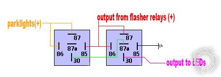
I have figured that I need 2 SPDT relays per side of the vehicle so the diagram below will be only for one side of the car. I'm sure that you guys can use your imagination for the other side of the car.
So without further ado, thoughts?
Replies:
Posted By: themartindobson
Date Posted: March 16, 2014 at 5:50 PM
Erm. Nevermind. I traced out the lines and if the park lights are on then it will have issues flashing. I might need to look deeper in to this
:(
Posted By: harryharris
Date Posted: March 16, 2014 at 6:40 PM
Soooo much simpler to use separate lights as do most car manufacturers, and also cheaper.  ------------- Test before boxing up.
Posted By: Ween
Date Posted: March 16, 2014 at 8:55 PM
Hi,
Use this: https://www.the12volt.com/relays/page5.asp#pts
Modify it by taking the '+12 volt from turn signal' and connecting it also to terminal 87. Don't use the connection labeled 'fused +12v'.
Connect the parking light wire to terminal 87a. Adding a resistor to the parking light input can reduce the current to the LED, dimming it.
You may need to adjust the values in the circuit depending on the relay used. Hope this helps.
Mark
Posted By: themartindobson
Date Posted: March 16, 2014 at 9:47 PM
@harryharris - Definitely easier, but not nearly as cool
plus I wasn't the one who built the car, lol.
@ween - thanks! I'll give that a try! I like the idea of using less relays to achieve the same output. Much appreciated!
Posted By: oldspark
Date Posted: March 16, 2014 at 11:07 PM
LOL - it's a fun problem isn't it?
Have a look at exLED's TPC Module Ver.2 - 2Color (2Way) Turn + Position Module.
They have other versions if that's not the correct behavior.
Otherwise to do what you want to do, you either need to move the flasher can so that the indicator switch switches relays that connect the can to the relevant flasher whilst disconnecting the park (or stop or reverse) signal to the LED/lamp; OR incorporate a timing function (ie, turns off the park/clearance/stop/reverse during the flasher on & off cycles).
Those exledusa units do the latter.
You could build your own version using a PICAXE 08 (08M2) for maybe $5 - $10 but that requires some DIY circuitry, programming (or cut&paste) skills, and a serial interface.
Posted By: themartindobson
Date Posted: April 12, 2014 at 12:14 PM
Alrighty, another question for you guys. Hopefully you can shed some light on this predicament we're having.
So we have all the wiring in the car hooked up right now and everything seems to be working flawlessly except for the turn signals.
Back story:
Front LED marker lights are these: https://www.pmlights.com/products.cfm?cId=1&fid=54&pId=1438#V168XA
We are having this light do a dual duty of Parklights and Turn Signals/Hazards Priority
Rear Lights are a dual filament incandescent bulb
We are having Filament 1 do: Parklights only
Filament 2 do: Brake lights with Turn Signal Priority
The front LED park lights are being controlled through the steering stalk and then goes in to the relay system that @ween mentioned in post #4.
The rear filament(2) is being controlled with a relay system that is very similar to the fronts but with the capacitor and resistor removed. We originally had it hooked up but removed the cap/resistor for troubleshooting.
--------
The hazard switch controls a DPDT relay to break open the feed coming from the steering stalk and put the hazard lines on the outputs to each corner light. This is working perfectly. Once the hazard switch comes on, all 4 lights start to blink perfectly.
However, when hazards are going we have found that when using non-LED based Flasher relays in our "keepitclean" fuse box this happens:
RF relay clicks on - stays on
LF relay clicks with the hazard flasher relay
RR relay clicks with the hazard flasher relay
LR relay clicks with the hazard flasher relay
Not sure why the RF relay only clicks on and stays on when the other three click with the hazard relay. I had a feeling that it was due to the LF capacitor.
---------------
Brake lights work as planned
Parklights work as planned.
Turn signals do not work without extra assistance from a test light on the pin 86 of one of the rear relays.
I have tried removing a rear relay and putting a jumper in the relay socket between pin 87 and pin 30 (basically bypassing the relay) here I have been able to get the turn signal on that side to work but we lose brake lights as they're pin 87a in the relay system.
I'm officially out of ideas on how to fix so hopefully you guys can think of something
.
Posted By: Ween
Date Posted: April 12, 2014 at 3:08 PM
Steering stalk/turn signal switch being used is from what vehicle?
Posted By: harryharris
Date Posted: April 12, 2014 at 4:25 PM
The answer to your last post lies within my first reply because I'm afraid I'm one jump ahead and many years of experience down the road.
You're either getting a voltage feedback from the LEDs or the relays are having a latching effect on each other.
The only way to solve your problem with LEDs is to have separate "bulbs".
-------------
Test before boxing up.
Posted By: oldspark
Date Posted: April 12, 2014 at 7:24 PM
Try a LED compatible flasher.
Or wire bulbs in parallel - at least for testing.
Posted By: themartindobson
Date Posted: April 13, 2014 at 9:48 PM
Turn signal switch is one of these: https://www.uapac.com/antique/lighting-and-electrical/switches/turn-signal-switch-steel-housing-a5007.html
No sure why it calls for the brake switch to go through the steering stalk though ??. That orange wire is not connected to anything and we're using a ball bearing switch on the brake switch that controls another relay that applies power to the brake lights. But I digress, the brake lights are working perfectly.
--------
@harryharris. I appreciate the input but I disagree that adding bulbs to have dedicated jobs are the only solution. My charger's turn signals double as park lights and many vehicles have a filament that does the double duty of brake lights and turn signals. We're just putting them both on one car. We get the turn signals working once a non-computer safe test light is applied to the rear bulb wires to increase the amount of draw on the turn signal wires that then activates the flasher relays. Unfortunately we don't want to have to sink bulbs under the dash to help increase the current draw that's necessary so I'm more curious if it could be that the rear SPDT relays aren't sensitive enough to trip.
--------
@oldspark - Unfortunately we have tried LED flashers. For the turn signal flasher, then for the hazard flasher, then both, then neither. No change. :(
Posted By: oldspark
Date Posted: April 13, 2014 at 11:00 PM
themartindobson wrote:
My charger's turn signals double as park lights and many vehicles have a filament that does the double duty of brake lights and turn signals. We're just putting them both on one car.
And there lies your solution - duplicate their switching and wiring. If it's not done by the flasher switch itself it is done by external relays - eg, one DPDT per side - and the flasher can is mounted AFTER the switch, not before it as with most vehicles.
If you do not want to add relays or reposition your flasher can, have a look at the exLED link I provided.
Else you could design your own equivalent circuit - I'd suggest a PICAXE 08 (08M2).
There is a possible circuit using JFETs but only if the LED/lamp to be flashed or modulated is ~50mA or less, but I suggest the above common options instead.
Posted By: themartindobson
Date Posted: April 13, 2014 at 11:41 PM
I was worried that might be the solution. Thanks! I guess this will be requiring some more in depth electrical engineering than what is normal.
Posted By: oldspark
Date Posted: April 14, 2014 at 1:43 AM
The point being that for a normal system, it cannot be done by mere relays - it needs a time delay to hold off the brake or park or reversing light (whatever) in between flashes.
And it can get complicated if changing the load on the flasher can since most places by law require fast or hyperflashing if either of the main flasher bulbs fails - hence they are load sensitive.
Mere timer activated relays are not, but that not how OEM flasher cans are designed.
To use merely relays, the switch turn on the RH or LH relays which in turn (1) connect the flasher can to the (front & rear) flashing bulbs & (2) isolate the bulb's other function (park or stop or reverse) but keep that function connected to the other side or front lights. Hence an SPST & SPDT relay - or one DPDT relay - per side when it involves rear flashers that combine with brake or reverse lights.
I was going to have my side and front flashers do a similar park & flash and essentially decided on a PIC 08M2 to do the smarts since it could use PWM to dim LEDs or bulbs, or dim (white) park LEDs adjacent to the flashing amber LEDs - something I note several manufacturers fail to do.
Posted By: harryharris
Date Posted: April 14, 2014 at 1:48 AM
The point being that for a normal system, it cannot be done by mere relays - it needs a time delay to hold off the brake or park or reversing light (whatever) in between flashes.
And it can get complicated if changing the load on the flasher can since most places by law require fast or hyperflashing if either of the main flasher bulbs fails - hence they are load sensitive.
Mere timer activated relays are not, but that's not how OEM flasher cans are designed.
Thanks Peter that was what I was trying to explain earlier, maybe howie ll has some input.
-------------
Test before boxing up.
Posted By: oldspark
Date Posted: April 14, 2014 at 3:06 AM
Nah - don't listen to that old fool. He's rude. Besides, he keeps correcting my mistakes!
And thanks for confirming what I was (trying!) to say. It sounds more eloquent coming from you.
As for a "normal" system, it can be done, but the flasher can is bridged out to that IGN +12V goes to the R-L flasher switch (not the pulsed flashing +12V that requires bulb loading).
The switch then activates whichever relay - or both if hazards - and the relay(s) connects the can to all flashing bulbs thru its 2 x NO contacts - ie, to rear, and front & side & dash.
The NC 87a connects the rears to their normal function - ie, brakes, reverse, parkers, etc.
And if the front is to be similar - ie, front parkers else flashers - the same is duplicated - else substituted if no rear combined bulb functionality exists in which case the dash indicator is taken off the rear lights. But if in addition to the rear, then another DPDT relay (I think) to similarly interconnect the can to the fronts (where the NC 87a is the park circuit) as well as connect the dash indicator to the can.
Using the rear-only stop/flasher as an example:
Switch to coil(s) 86 with 85 to GND.
30 to rear lights; 87a to stop signal; 87 to flasher can output.
And 30 to front flasher and 87 to flasher can output
Hence when energised, the can sees its normal front & rear bulbs and will hyperventilateflash if either fail.
Of course if substituting LEDs you have the typical hyperflash issue. Some electronic flasher cans can be modified by changing the resistor that forms a voltage divider with the high wattage low ohmage resistor (wire) that sits between the flasher output and the L (lamp) output terminal.
They are typically set for a few hundred mV across that wire (shunt resistor). If a bulb blows, the lower current means a lower shunt voltage hence triggering hyperflashing. (Easy to do with electronics, but fun to figure out how they did it with the old electro-mechanical flashers!)
BTW - I had to do that to my old 1964 sedan and current ute which have combined flasher/reverse. The switching was originally part of the flasher switch, but I substituted newer combo switches (I HATE floor dip switches!) and they only had the typical 3-wire switch - ie, in from the can output, and then R or L out to the lamps.
These days I'd use exLED type circuits but have them drive relays instead of LEDs if I were using OEM bubs.
And this is a topic I love. To see the plethora of people that keep trying to do it with plain relays without changing the flasher can location or without inter-flash hold-off delays...
For some it takes several trials and errors before they see else accept the advice given.
Posted By: harryharris
Date Posted: April 14, 2014 at 3:09 AM
Which is why I suggested two separate lighting units in the first place; so much less grief.
-------------
Test before boxing up.
Posted By: oldspark
Date Posted: April 14, 2014 at 3:26 AM
ABSOLUTELY!
I wonder why the Japs separated their reverse light into a separate dedicated clear lensed lamp. Because they are not stupid!
PS - even if it's 2 separate single filament bulbs in the same fitting... ABSOLUTELY!
Posted By: harryharris
Date Posted: April 14, 2014 at 4:45 AM
It's ONLYNorth America that keeps them together as with amber running lights.
The rest of the world uses white running lights with amber front, mid and rear indicators.
-------------
Test before boxing up.
Posted By: oldspark
Date Posted: April 14, 2014 at 7:50 AM
I do believe in all amber flashers. Though recently adding amber/orange edge emitting LEDs to the inside of my front clear flasher, I also changed the bulb/socket from its former flasher/park dual filament bulb to dedicated amber bulb (I should have converted to amber LED flasher bulbs instead!).
The parking lights were migrated to the outer hi/low beams years ago.
Tho our fronts (clearance/parkers) are clear (white), I have been contemplating amber. I rather like the look & IMO amber stands out far better - even in our hot dry to cold drizzly climate.
In fact being clear lensed, I could have amber flashers and amber or white parkers, tho I'd probably make the white a full brightness.
Of course any parker - whether amber or bright or dim white - would totally extinguish during flashing as per those exLED module variants; after all, unlike certain manufacturers and authorities, I'm not stupid (or should I say, I see the inevitable).
Rear side clearance lights... maybe amber, or maybe red, or both adjacent to each other. And the possibility of amber also flashing (maybe with red off, tho that should not be necessary).
Oddly enough I used to dislike stateside or north American combined stop/flashers.
However now I find them acceptable and possibly aesthetically pleasing, and I see the (aesthetic?and) manufacturing advantage of a single red lamp that does all 3 functions - ie, stop, tail & flasher.
The rear red flasher makes it obvious which end of the vehicle your are observing and I wonder if that is an advantage in compromised visibility (whether weather conditions or observer shortcomings).
Reverse lights as usual should be clear/white.
As I've looked at all the above, recently I have concluded clear lenses (as is the trend of modern vehicles) and the use of programmable RGB SMT LEDs which are now readily available. Hence a lens can be any color and any brightness and flashing or modulated at any rate, and probably be controlled by mere a $3 PICAXE 08M2 or one of its larger and almost as cheap siblings.
I almost look forward to the day some Officer pulls me over for having arguably illegal amber FRONT parkers. I then hit the preconfigured "legal" button and question how she or he could have confused my white parkers as being amber...
Alas, I did digress. But it may be food for thought for hotroders and other vehicle modifiers. And of course vehicle legislators, tho I find they learn thru experience an NOT advice.
Posted By: harryharris
Date Posted: April 14, 2014 at 7:53 AM
Note European market cars use orangey/red rear fog lights for poor weather conditions.
-------------
Test before boxing up.
|