Sorry Steve, I missed this thread.
And FTR, IMO you didn't stir any dust - you merely confused some idiot of an oldFart.


(Or should I say, added to oldFart's confusion?)
IMO your question was answered, but just to make sure...
From
webpager's type of relay or suggestions p2 and the following diagram:
steve392 wrote:
Oldspark mentioned that a diode can be inserted between 87 and 86 to energize the coil. I'm not sure if that was at the "master" relay or at each of the "slaves", but wouldn't that negate the switch (either momentary or s.p.s.t.)? It seems to me that once 87 is energized, either by the car being started and running in the case of the master relay, or by the master relay energizing the slave relays, the diode between 87 and 86 bypasses the switch entirely? Maybe another way to put it is if there is a diode between 87 and 86, what does the switch do?
My original answer but now paraphrased...
Your assessment is correct.
(And you can stop reading here, but FYI...)
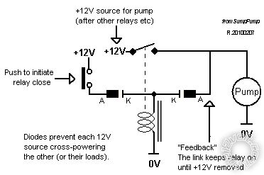
My comment re the diode was because in the diagram above, the momentary switch carries the full load current until the 30-87 contacts close (probably between 1 - 5 mSecs later).
I then mentioned a similar
latching relay circuit diagram which has an OFF switch added (see below). (
webpager removes +12V power from the entire circuit to turn off the latched relay.)
And in that on-off latching digram, to prevent load power thru the on & off switches, the diodes are added.
My circuit was used for a water pump circuit. Low current reed switches were used for the on & off switches (specifically automotive brake-fluid reservoir float switches.) The relay turned on a water pump.
Without the diodes, if the relay is open, the motor/load current goes thru the switches. And a 2A etc motor will destroy reed switches.
Hence the diodes, tho only the only the OFF switch's diode is required. (I had some reason for including the ON diode but I suspect that was simply for symmetry or modularity - ie, pre-wire all switches with diodes and it doesn't matter which switch is used for either leg. Simpler spare parts etc - ie, one size fits all)
FYI - I used the pump and circuit as a 'sump pump' - ie, I blocked off my gully trap (water outlet) and dropped in the pump and
stick with the upper and lower limit switches to water the garden when our 7 year drought entered its 13th year.
It can be used as a tank circuit - ie, to keep a tank filled to a certain level - simply by turning the
switch-stick upside down.
IMO it was a brilliant and original circuit. Later I found it was not original, but hence even more bewilderment as to why all 4 or more equivalent circuits that I found in electronics magazines etc had complex circuitry. They already had the switches, they merely needed a plain SPST relay.
Anyhow, does that solve your requirement? As I said, your reply in the other thread was correct. And I should have stopped there, but to clarify or correct my original reply (and maybe brag, or admit embarrassment?)
I should add that I confused
webpager's thread with another, hence my diagrams. My only valid comment was that the momentary on button carries the full load until the relay closes. But since that
full load was merely a handful of (slave) relay coils, in retrospect I should never have posted any reply.