power locks relay
Printed From: the12volt.com
Forum Name: Relays
Forum Discription: Relay Diagrams, SPDT Relays, SPST Relays, DPDT Relays, Latching Relays, etc.
URL: https://www.the12volt.com/installbay/forum_posts.asp?tid=138052
Printed Date: May 14, 2026 at 10:24 AM
Topic: power locks relay
Posted By: aronmigz
Subject: power locks relay
Date Posted: December 25, 2014 at 12:38 PM
Im trying to install power locks on ny 88 toyota pickup with no luck. The only cinfiguration of wiring that powers either lock or unlock only does one of both AT ALL. I tried atleast 4 different wiring setups for the relays. Im no newbie to mechanics but this relays are kicking my azz. I got an alarm installed and attempted to do the locks but ill be lucky to get unlock going
The only wiring i got working is as follows on both relays..
85----12v fused
86----ground to chassis
30----neg. Pulsed from alarm
87----to door lock actuator(lock/unlock)
-------------
Aron Migz
Replies:
Posted By: i am an idiot
Date Posted: December 25, 2014 at 5:56 PM
Posted By: shark mobile
Date Posted: December 25, 2014 at 6:50 PM
Door control relay is located behind the driver dash speaker. From my info they are negative triggers so no need for relays...BROWN / white for
-------------
Solder, tape, repeat!
Posted By: shark mobile
Date Posted: December 25, 2014 at 6:53 PM
Whoops that was a case of big thumbs and a little phone! BROWN / white is lock (-). Unlock is pink/white also (-)....behind the drivers dash speaker...hope that helps
-------------
Solder, tape, repeat!
Posted By: aronmigz
Date Posted: December 25, 2014 at 7:57 PM
i am an idiot wrote:
Aftermarket actuators?
If so: https://www.the12volt.com/doorlocks/page3.asp#arp
Yes aftermarket with green and blue wires ------------- Aron Migz
Posted By: aronmigz
Date Posted: December 25, 2014 at 8:02 PM
shark mobile wrote:
Whoops that was a case of big thumbs and a little phone! BROWN / white is lock (-). Unlock is pink/white also (-)....behind the drivers dash speaker...hope that helps
Sorry i shoulfve mentioned its a 88 toyota pickup with no original powerlocks installed so no original neg pulse lines to tap into ------------- Aron Migz
Posted By: aronmigz
Date Posted: December 25, 2014 at 8:25 PM
When i wire the relays with the output to the actuators on 87 and neg pulse in on 30, it seems to operate unlock only.
As soon as i connect power it energizes the coil and the relay clicks. Which is good but this cause my relays to be hot all the time..
-------------
Aron Migz
Posted By: jkxmlr
Date Posted: December 25, 2014 at 9:20 PM
https://www.the12volt.com/relays/relays.asp Read and comprehend this! I personally like to use 30 as my power input. This is because 87 and 87a are the two poles being switched by the relay. These are the poles outputting the work, i.e.; going to your actuators. (30 and 87 interchangeable, as end result is the same.) 85 and 86 are the connectors that change the poles. Pulse from unit to one or the other, other is ground/hot as needed per negative pulse or positive pulse.
Posted By: howie ll
Date Posted: December 25, 2014 at 11:25 PM
Actually, use a dedicated lock timer relay from Spall, MES (the older blue is best).
Also only one master is needed (5 wire) for driver door .
You need a timer because when the master actuator goes back to rest the NEG going switched wire STAYS NEG.
If you're just using 2 wire motors then you won't need a relay, use a Spall window switch effectively a 2 pole changeover momentary centre off switch, readily available from Mouser etc.
-------------
Amateurs assume, don't test and have problems; pros test first. I am not a free install service.
Read the installation manual, do a search here or online for your vehicle wiring before posting.
Posted By: aronmigz
Date Posted: December 26, 2014 at 12:02 AM
Thanks for all the help guys.
-------------
Aron Migz
Posted By: aronmigz
Date Posted: December 26, 2014 at 12:04 AM
howie ll wrote:
Actually, use a dedicated lock timer relay from Spall, MES (the older blue is best).
Also only one master is needed (5 wire) for driver door .
You need a timer because when the master actuator goes back to rest the NEG going switched wire STAYS NEG.
If you're just using 2 wire motors then you won't need a relay, use a Spall window switch effectively a 2 pole changeover momentary centre off switch, readily available from Mouser etc.
If i just go with a 2 pole switch, how am i gonna wire it to my alarm to unlock and lock from the remote? ------------- Aron Migz
Posted By: howie ll
Date Posted: December 26, 2014 at 12:21 AM
With a 2 pole switch, must be momentary with a centre off, wire it follow the diagram that Mr. Idiot posted:-
Use two X 5 pin relays.
NEG to switch then one side to relay 85.
87a to ground.
30 and 86 fused, 12V+ constant, 15 amps for two actuators, 25 for four.
30 Green.
Other switch output to 85.
87a to ground.
30 and 86 shared with relay above.
30 to blue.
-------------
Amateurs assume, don't test and have problems; pros test first. I am not a free install service.
Read the installation manual, do a search here or online for your vehicle wiring before posting.
Posted By: aronmigz
Date Posted: December 26, 2014 at 12:25 AM
Thanks alot. Im gonna give that a try
-------------
Aron Migz
Posted By: howie ll
Date Posted: December 26, 2014 at 12:27 AM
This is the first time you've you've mentioned an alarm, if you fail to tell us how can we teach you?
Lock and unlock (NEG) to 85 on either relay, you'll probably need to turn some of these lock and unlock wires around so don't solder until everything works.
I really can't help any more unless you tell us what kind of alarm, make and model and whether there are two or six lock/unlock wires coming from the alarm, you'll also now need to diode the relays, 1N4004 across 86 and 85, band to 86.
-------------
Amateurs assume, don't test and have problems; pros test first. I am not a free install service.
Read the installation manual, do a search here or online for your vehicle wiring before posting.
Posted By: aronmigz
Date Posted: December 26, 2014 at 12:55 PM
Okay well its a presitge alarm. Its a 3 wire neg. pulsed door lock blue for unlock,green lock, blue/green secondary unlock.
The door lock actuators 2 wires. Green and blue.
-------------
Aron Migz
Posted By: i am an idiot
Date Posted: December 26, 2014 at 9:29 PM
I really love the way I can become invisible at will.
Posted By: howie ll
Date Posted: December 26, 2014 at 11:54 PM
Craig, ??
-------------
Amateurs assume, don't test and have problems; pros test first. I am not a free install service.
Read the installation manual, do a search here or online for your vehicle wiring before posting.
Posted By: i am an idiot
Date Posted: December 27, 2014 at 10:53 AM
i am an idiot wrote:
Aftermarket actuators?
If so: https://www.the12volt.com/doorlocks/page3.asp#arp
Posted By: howie ll
Date Posted: December 27, 2014 at 11:04 AM
OP, please use the above link, it explains everything.
-------------
Amateurs assume, don't test and have problems; pros test first. I am not a free install service.
Read the installation manual, do a search here or online for your vehicle wiring before posting.
Posted By: howie ll
Date Posted: December 27, 2014 at 2:38 PM
Or try this:- add_actuators_with_a_control_switch.png------------- Amateurs assume, don't test and have problems; pros test first. I am not a free install service.
Read the installation manual, do a search here or online for your vehicle wiring before posting.
Posted By: aronmigz
Date Posted: December 27, 2014 at 2:54 PM
So i been working on this for about a week now..i tried the normal way the package says to wire a relay, the 3 wire, 5 wire and nothing..idk what im missing here..the only it ever seems to make the actuator move is if i keep 85 and 86 energized 24/7... And im kinda iffy bout doing that.
-------------
Aron Migz
Posted By: howie ll
Date Posted: December 27, 2014 at 2:55 PM
Just follow my last diagram.
-------------
Amateurs assume, don't test and have problems; pros test first. I am not a free install service.
Read the installation manual, do a search here or online for your vehicle wiring before posting.
Posted By: aronmigz
Date Posted: December 27, 2014 at 2:59 PM
Ill give it a shot.. Im close to saying love it and weld the doors up and slide in and out like the dukes of hazard..aint gotta play with faulty locks and handles again
-------------
Aron Migz
Posted By: howie ll
Date Posted: December 27, 2014 at 3:01 PM
Leave the work, have a cup of tea/coffee, relax. Go back tomorrow and copy that diagram, BTW make surer you have a 1 pole 2 way, aka changeover switch, momentary, centre off.
-------------
Amateurs assume, don't test and have problems; pros test first. I am not a free install service.
Read the installation manual, do a search here or online for your vehicle wiring before posting.
Posted By: aronmigz
Date Posted: December 27, 2014 at 3:03 PM
Haha best advicd ever.. Forget a coffee ima smoke me a joint and chill..tomorrows my day off so ill have plenty of sunlight to dig in
-------------
Aron Migz
Posted By: davep.
Date Posted: December 28, 2014 at 2:39 AM
Here. This is IAAI's linked diagram.

Posted By: aronmigz
Date Posted: December 28, 2014 at 2:43 AM
davep. wrote:
Here. This is IAAI's linked diagram.
Tried that one too.. No luck. I know the actuators work, i can get to both unlock and lock but never at the same time or it does it really rapidly. No where fast enough to open the door that quickly lol ------------- Aron Migz
Posted By: davep.
Date Posted: December 28, 2014 at 12:03 PM
aronmigz wrote:
davep. wrote:
Here. This is IAAI's linked diagram.
Tried that one too.. No luck. I know the actuators work, i can get to both unlock and lock but never at the same time or it does it really rapidly. No where fast enough to open the door that quickly lol
Then your connections aren't correct. You've made a mistake, and are overlooking it during trouble-shooting. That's all it can be.
The above diagram is correct. It works. OEM's use it too in millions of vehicles produced all over the world.
I'm wondering if you have an understanding of how the relay numbers correlate to how a relay operates? The regulars on here know the numbers intuitively. If you don't, then it's difficult to deduce how the circuit is supposed to work.
The relay has two states: Energized, and OFF.
85 and 86 are the coil. 85 (-), 86 (+). These are the "control".
When the coil is ON, 30 is connected to 87.
When the coil is OFF, 30 is connected to 87a.
Perhaps taking the mystery out of how a relay functions will help you understand how this circuit operates. And that should help you find your mistake in the wiring.
Now I'm going invisible too.
Posted By: howie ll
Date Posted: December 28, 2014 at 12:11 PM
X2 with Davep. Check your wiring, make sure your getting NEG on lock and unlock for about 1/2 second each from the alarm green and blue.
Wire the relays then simply ground 85 on each. If that works wire up the switch, which MUST be momentarily if that works connect the alarm wires.
Bet you've either made a simple wiring error or you have the wrong type of switch.
As Davep says, I've been using this type of set-up since the early 1980s, my mod to the original diagram allows for a switch but the type of switch is VERY IMPORTANT.
-------------
Amateurs assume, don't test and have problems; pros test first. I am not a free install service.
Read the installation manual, do a search here or online for your vehicle wiring before posting.
Posted By: howie ll
Date Posted: December 28, 2014 at 12:28 PM
This is the cheapest way to switch:-
https://www.radioshack.com/mini-spst-0-5-amp-momentary-switch-4-pack/2751547.html#start=116&sz=12
-------------
Amateurs assume, don't test and have problems; pros test first. I am not a free install service.
Read the installation manual, do a search here or online for your vehicle wiring before posting.
Posted By: howie ll
Date Posted: December 28, 2014 at 12:37 PM
And here's another but you won't be using all of the terminals:-
https://www.radioshack.com/nte54-118-15a-snap-in-nylon-rocker-momentary-switch/55050533.html#start=40&sz=12
And now for a blast of common sense:-
1) If you can set your alarm for auto-lock why in the name of heaven do you need a switch?
2) Doesn't your alarm give you an installation guide showing you how to wire relays for locks?
-------------
Amateurs assume, don't test and have problems; pros test first. I am not a free install service.
Read the installation manual, do a search here or online for your vehicle wiring before posting.
Posted By: aronmigz
Date Posted: December 28, 2014 at 12:50 PM
howie ll wrote:
And here's another but you won't be using all of the terminals:-
https://www.radioshack.com/nte54-118-15a-snap-in-nylon-rocker-momentary-switch/55050533.html#start=40&sz=12
And now for a blast of common sense:-
1) If you can set your alarm for auto-lock why in the name of heaven do you need a switch?
2) Doesn't your alarm give you an installation guide showing you how to wire relays for locks?
Okay to answer your questions.. I was not plannin on using a switch its pointless in a 2 door truck if the alarm is supposed to lock and unlock.
And no the alarm only has diagram for alarm wiring. It shows a 2 wire harness with lock and unlock and its labeled neg pulse unlock or lock. ------------- Aron Migz
Posted By: howie ll
Date Posted: December 28, 2014 at 12:54 PM
Sorry, your fault for not mentioning an alarm in the first place, use the diagram posted by Idiot, Davep etc.
4 pages to wire a pair of relays? Blimey.
-------------
Amateurs assume, don't test and have problems; pros test first. I am not a free install service.
Read the installation manual, do a search here or online for your vehicle wiring before posting.
Posted By: aronmigz
Date Posted: December 28, 2014 at 12:55 PM
davep. wrote:
aronmigz wrote:
davep. wrote:
Here. This is IAAI's linked diagram.
Tried that one too.. No luck. I know the actuators work, i can get to both unlock and lock but never at the same time or it does it really rapidly. No where fast enough to open the door that quickly lol
Then your connections aren't correct. You've made a mistake, and are overlooking it during trouble-shooting. That's all it can be.
The above diagram is correct. It works. OEM's use it too in millions of vehicles produced all over the world.
I'm wondering if you have an understanding of how the relay numbers correlate to how a relay operates? The regulars on here know the numbers intuitively. If you don't, then it's difficult to deduce how the circuit is supposed to work.
The relay has two states: Energized, and OFF.
85 and 86 are the coil. 85 (-), 86 (+). These are the "control".
When the coil is ON, 30 is connected to 87.
When the coil is OFF, 30 is connected to 87a.
Perhaps taking the mystery out of how a relay functions will help you understand how this circuit operates. And that should help you find your mistake in the wiring.
Now I'm going invisible too.
Whaaaat?! Really?! U dont say?! Is that how a relay works?
Geez id think after wiring hids, a 4 pump hydraulic set up, shaved door handles, and trunk poppers in cars 10 years older i would know how a simple relay works. Thanks for unlocking that mystery, ill call off scooby and the gang.
Dude so be sarcastic, but a lil common sense would be if you can read a diagram. You probably understand how it works.
But thanks anyway ------------- Aron Migz
Posted By: howie ll
Date Posted: December 28, 2014 at 12:57 PM
Simple, we're not being sarcastic mate, just frustrated, test all your stages, this is a half hour job from scratch or go and buy a DEI 451, 10 minutes.
Insulting us won't help, the more us pros see things like "I built a Saturn 5 and an Enterprise 1701 in my back yard" the more we see a cry for help, are you taking any advice?
-------------
Amateurs assume, don't test and have problems; pros test first. I am not a free install service.
Read the installation manual, do a search here or online for your vehicle wiring before posting.
Posted By: aronmigz
Date Posted: December 28, 2014 at 12:58 PM
howie ll wrote:
Sorry, your fault for not mentioning an alarm in the first place, use the diagram posted by Idiot, Davep etc.
4 pages to wire a pair of relays? Blimey.
Howie.. Read the very first post clearly. I stated that the neg input into the relay was being supplied from a alarm neg pulsed.
Not too sound like a dick to you and thanks for the input. But alot of ppl are reading and jumping to the conclusion i didnt state an alarm. I stated all facts. ------------- Aron Migz
Posted By: howie ll
Date Posted: December 28, 2014 at 1:01 PM
Quite true for which I apologise but..... this relay configuration is used by the million weekly by auto makers and by the thousand weekly by people like us, AGAIN CHECK/TEST ALL YOUR STAGES.
-------------
Amateurs assume, don't test and have problems; pros test first. I am not a free install service.
Read the installation manual, do a search here or online for your vehicle wiring before posting.
Posted By: aronmigz
Date Posted: December 28, 2014 at 1:04 PM
To break it down. Heres how i been wiring it.
2- 5 post 30 amp relays..identical from oreillys.
------------------------
86- Fused 12v input on both relays
85- Neg pulsed input from alarm
87- fused 12v input on both relays
30- to actuators.
Annnnnnnnnd nothin...
-------------
Aron Migz
Posted By: aronmigz
Date Posted: December 28, 2014 at 1:08 PM
Only response i got from this nightmare of a problem pyrchased off ebay...
86 12v fused
85 constant ground
So that in turn would keep the coil energized or on. ALL THE TIME.
30 negative pulsed input from alarm
87 output to actuators
But the only thing that happens is i get the actuator to unlock not lock.
-------------
Aron Migz
Posted By: aronmigz
Date Posted: December 28, 2014 at 1:11 PM
So i then thought what if my alarm is putting out a neg pulse but my ebay actuators require a positive power source.
So i went out got another relay and wired
86 and 87 to fused 12v
85 neg pulse from alarm
30 to 86 input on relays to operate power the door locks
-------------
Aron Migz
Posted By: aronmigz
Date Posted: December 28, 2014 at 1:15 PM
Thats whats freakin blowing my lovein mind... A million pages on the damn web, forum how tos, youtube videos and still this damn thing dont work. Its wizing me off. Whats the point of having a alarm if i still gotta open the door with a key.
-------------
Aron Migz
Posted By: i am an idiot
Date Posted: December 28, 2014 at 1:21 PM
It works. You have something wired wrong. You probably have 30 and 87 backwards.
Posted By: aronmigz
Date Posted: December 28, 2014 at 1:24 PM
i am an idiot wrote:
It works. You have something wired wrong. You probably have 30 and 87 backwards.
Ive wired every post every which way imaginable.. Reversed 85 and 86, 30 and 87. Jumped 86 and 87 with 12v, jumped 86 and 30 with 12v and 87 leading to the actuators.
------------- Aron Migz
Posted By: aronmigz
Date Posted: December 28, 2014 at 1:27 PM
Ill redo the wiring today and post pics of it.
-------------
Aron Migz
Posted By: aronmigz
Date Posted: December 28, 2014 at 3:25 PM
howie ll wrote:
Quite true for which I apologise but..... this relay configuration is used by the million weekly by auto makers and by the thousand weekly by people like us, AGAIN CHECK/TEST ALL YOUR STAGES.
Tried it again and i blew a fuse then fried a 12v line ------------- Aron Migz
Posted By: i am an idiot
Date Posted: December 28, 2014 at 3:52 PM
What are you connecting to 87A. I see no mention of 87A when you say what you are connecting.
Posted By: aronmigz
Date Posted: December 28, 2014 at 3:56 PM
i am an idiot wrote:
What are you connecting to 87A. I see no mention of 87A when you say what you are connecting.
86 to 12v fused 15amps
87 to 12v fused
85 to alarm neg.
87a to ground(same ground my wiring is on)
30 to actuators
------------- Aron Migz
Posted By: howie ll
Date Posted: December 28, 2014 at 4:55 PM
Alarm negative or lock/unlock for 85?
"Tried it again and i blew a fuse then fried a 12v line"
87a and 30 wrong way round.
-------------
Amateurs assume, don't test and have problems; pros test first. I am not a free install service.
Read the installation manual, do a search here or online for your vehicle wiring before posting.
Posted By: aronmigz
Date Posted: December 28, 2014 at 5:04 PM
Im doing it just like the diagram says... 87a to ground... Output to actuators on 30... Fried wires..
If i turn 30 and 87a around. When ON 30 which is ground, will connect with 87 which is 12v and 87a will be OFf.if im correct..
-------------
Aron Migz
Posted By: howie ll
Date Posted: December 28, 2014 at 5:18 PM
30 to actuator (motor wire) normally sits at rest on ground , connected to 87a.
86 and 87 are constantly at at 12 volts.
When 85 is grounded, the link between 87a is broken, feed to 30 is switched to 87 (12V+), meanwhile the other relay is "inert" thus the other motor wire still goes to ground, thus the actuator will move in one direction.
Removing the ground (85) pulse from the first relay and applying it to the other relay will move the actuator in the other direction.
You need to try this first, then test the alarm's lock and unlock outputs, test one part at a time.
Make sure you haven't made a wiring error in shorting one of those motor wires, e.g. trapped by a door stay, window channel or winder mechanism.
When installing actuators, I fit the motors, then run the wiring into the car and I test, one side to POS, the other to NEG then I reverse those connections, if the motor works and runs easily I can box up the door and go to the next stage. The trick is to test at each stage.
I've told you all I can, I'm pretty sure the others agree, think you're on your own now.
-------------
Amateurs assume, don't test and have problems; pros test first. I am not a free install service.
Read the installation manual, do a search here or online for your vehicle wiring before posting.
Posted By: davep.
Date Posted: December 28, 2014 at 5:38 PM
aronmigz wrote:
Whaaaat?! Really?! U dont say?! Is that how a relay works?
Geez id think after wiring hids, a 4 pump hydraulic set up, shaved door handles, and trunk poppers in cars 10 years older i would know how a simple relay works. Thanks for unlocking that mystery, ill call off scooby and the gang.
I wasn't being sarcastic at all.
I figured that because you haven't been able to make a simple polarity-reversing 5-wire lock circuit work in two weeks and FIVE pages that the reason could only be that you don't know how this stuff works. So I tried to help. I was serious.
I have a new thought as to what's going on here. You're just a troll messing with us. No one is this stupid. No one needs 2 weeks and 5 pages to figure out a 5-wire reversing polarity lock circuit. You have it working, but are entertaining yourself by continuing to mess with us. Seriously, I think this is it, guys. He's just f'in with us now.
I'm out.
Posted By: aronmigz
Date Posted: December 28, 2014 at 6:44 PM
howie ll wrote:
30 to actuator (motor wire) normally sits at rest on ground , connected to 87a.
86 and 87 are constantly at at 12 volts.
When 85 is grounded, the link between 87a is broken, feed to 30 is switched to 87 (12V+), meanwhile the other relay is "inert" thus the other motor wire still goes to ground, thus the actuator will move in one direction.
Removing the ground (85) pulse from the first relay and applying it to the other relay will move the actuator in the other direction.
You need to try this first, then test the alarm's lock and unlock outputs, test one part at a time.
Make sure you haven't made a wiring error in shorting one of those motor wires, e.g. trapped by a door stay, window channel or winder mechanism.
When installing actuators, I fit the motors, then run the wiring into the car and I test, one side to POS, the other to NEG then I reverse those connections, if the motor works and runs easily I can box up the door and go to the next stage. The trick is to test at each stage.
I've told you all I can, I'm pretty sure the others agree, think you're on your own now.
Well i guess i dont know what im doing then because i wired it just how the diagram stated. Just as you mentioned and all im doing is frying wires and burning fuses and wasting money.. love it.. Not buying from china anymore and ima just go with door poppers. Simple. Done it before no problems. ------------- Aron Migz
Posted By: i am an idiot
Date Posted: December 28, 2014 at 8:28 PM
I think Davep can read the diagram and make it work.
Posted By: aronmigz
Date Posted: December 28, 2014 at 8:35 PM
i am an idiot wrote:
I think Davep can read the diagram and make it work.
But the question is why am i blowing fuses and burning wires only when 86 and 87 have 12v and 87a grounded.
As soon as i connect the power.. Fuse blows.. ------------- Aron Migz
Posted By: i am an idiot
Date Posted: December 28, 2014 at 8:39 PM
The pictures you mentioned the other day will probably help us figure it out.
Posted By: aronmigz
Date Posted: December 28, 2014 at 8:47 PM
i am an idiot wrote:
The pictures you mentioned the other day will probably help us figure it out.
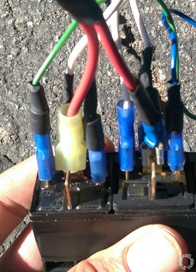
The white wires are 12v supplying power to 86 an 87. Blue and green wires are 85 neg. Pulsed from alarm. The fat red wire on 87a is ground(yes i know should be black, but this makes it easier to swap post to posts.
------------- Aron Migz
Posted By: i am an idiot
Date Posted: December 28, 2014 at 9:20 PM
Are you sure that there is an 87A? Make sure that your relays do not have 2 87s.
Posted By: howie ll
Date Posted: December 29, 2014 at 8:26 AM
One very last thought, test the motor wires, apply each end to live, see if you;ve shorted a wire.
You'll know if you place a 10 amp fuse on the live feed and it blows it.
-------------
Amateurs assume, don't test and have problems; pros test first. I am not a free install service.
Read the installation manual, do a search here or online for your vehicle wiring before posting.
Posted By: i am an idiot
Date Posted: December 29, 2014 at 3:13 PM
My money is on the relay to the right of the picture has 2 87s I can not see because the terminal is in the way. But notice that it is a different style relay than the one on the left.
Posted By: howie ll
Date Posted: December 29, 2014 at 3:20 PM
87 X 2, 87b would both blow fuses etc. first rule, look at the terminal markings and configuration.
-------------
Amateurs assume, don't test and have problems; pros test first. I am not a free install service.
Read the installation manual, do a search here or online for your vehicle wiring before posting.
Posted By: i am an idiot
Date Posted: December 30, 2014 at 1:50 PM
I am real curious to see what the problem was.
Posted By: howie ll
Date Posted: December 30, 2014 at 1:53 PM
Will we ever be told?
-------------
Amateurs assume, don't test and have problems; pros test first. I am not a free install service.
Read the installation manual, do a search here or online for your vehicle wiring before posting.
Posted By: aronmigz
Date Posted: December 30, 2014 at 3:10 PM
I checked the relays this morning.. I got 3..1 of em came with the alarm for started disable.. But dont need that.. And that one has 87a labeled on the replay.. The other 2 from oreillys on the packaging says 87a... On the relay only shows 2 87's and the armature per a relay...so i guess i got 2 87s n thats why its blowing fuses on those relays..
But why the hell does the package say 87a but the part ddont have 87a just 2 87s
-------------
Aron Migz
Posted By: howie ll
Date Posted: December 30, 2014 at 3:14 PM
Test it physically, see if you have continuity at rest between the 87s.
Remember when I posted that line about physically checking?
Also the comment about 87b and 2 X 87?
-------------
Amateurs assume, don't test and have problems; pros test first. I am not a free install service.
Read the installation manual, do a search here or online for your vehicle wiring before posting.
Posted By: aronmigz
Date Posted: December 30, 2014 at 3:24 PM
Whats 87b? is that the second 87??
Ill test it tomorrow... I git work in a few
-------------
Aron Migz
Posted By: howie ll
Date Posted: December 30, 2014 at 3:30 PM
2 X 87 means they are common I.e. connected, 87b means internal diode separated.
Please read up about relays, this is all too basic as was your original problem, thanks to Mr. I for finding the solution.
-------------
Amateurs assume, don't test and have problems; pros test first. I am not a free install service.
Read the installation manual, do a search here or online for your vehicle wiring before posting.
Posted By: i am an idiot
Date Posted: January 01, 2015 at 6:01 PM
Howie, I have never seen or heard of an 87B. Relays with 2 x 87 or 87B or SPST devices. The difference between the 2 are just as you stated, the 2 87s are still both connected when the relay is at rest. The ones with 87B, the 87B is not connected to the 87 when the relay is at rest. I guess if you had an application using 2 other relays to control 2 separate devices, you could parallel the 87 and 87B each with one of the other relays and have a 1 or 2 situation using the 2 relays and using the 87B relay you could have a 1 and 2 with a single input.
So this is what I learned on the first day of the new year. Hopefully the rest of the year will be as educating as the first. Thanks, and Happy New Year everyone.
Posted By: davep.
Date Posted: January 01, 2015 at 9:46 PM
I hadn't heard of an "87b" either until Howie posted this. And the "diode isolated" was also confusing. So I researched it.
The dual 87 has one armature contact. The two 87's are common to each other internally.
The 87b has two armature contacts. 87 and 87b are isolated until relay is energized. (But there are no diodes involved).
If the OP in this thread had had an 87b relay, he wouldn't have smoked wires and blown fuses until the relay was energized, but his circuit still wouldn't have worked as intended.
I too learned something this first day of the new year. Thanks, and Happy New Year.


Posted By: howie ll
Date Posted: January 02, 2015 at 4:11 AM
And I wasn't sure how the 87b worked so I said diode, rather daft really considering up to say 30 amps load.
Seen them originally many years ago when Clifford packed them with early alarms for Euro twin indicator circuits.
I've also seen 4 and 5 pin where the pins are in different configuration.
The whole point of this thread is look!
-------------
Amateurs assume, don't test and have problems; pros test first. I am not a free install service.
Read the installation manual, do a search here or online for your vehicle wiring before posting.
Posted By: i am an idiot
Date Posted: January 02, 2015 at 7:25 PM
Excellent application for an 87B device. Light flash on a Beamer.
|

