Polarity sensing 12VDC relay system
Printed From: the12volt.com
Forum Name: Relays
Forum Discription: Relay Diagrams, SPDT Relays, SPST Relays, DPDT Relays, Latching Relays, etc.
URL: https://www.the12volt.com/installbay/forum_posts.asp?tid=139042
Printed Date: May 14, 2026 at 9:22 AM
Topic: Polarity sensing 12VDC relay system
Posted By: mjhinno
Subject: Polarity sensing 12VDC relay system
Date Posted: June 01, 2015 at 8:04 AM
Boat has poorly designed high current 12VDC electric hatch lift actuators where all current for 2 motors (1 per side) runs through operator panel switch and harness. Voltage drop makes motors slow and run at different speeds. Termination end has motors wired parallel to 2 leads that switch polarity depending on op. panel switch position.
Is it possible to design a relay system where above 2 leads are control circuit only to actuate relays/contactors that will switch polarity of current (supplied by fused feed direct from batteries) to motors depending on the polarity coming from control circuit? Don't want to run more wiring from operator panel back to hatch if I can avoid it. Thank you in advance.
Replies:
Posted By: mjhinno
Date Posted: June 01, 2015 at 8:06 AM
Sorry-doubt its relevant, but this is a 23 ft. 1995 Mariah Talari Z
Posted By: davep.
Date Posted: June 01, 2015 at 12:16 PM
I would do it this way: 2 relays required. One will be for UP, and one will be for DOWN.
Note: All wiring on 30, 87, and 87a must be capable of carrying the full load of both actuators. My experience is that #10 should be adequate. Fuse or Circuit Breaker for 30 Amps for #10 wire.
UP:
87 = Hot at all times.
87a = Ground
30 = To both actuators, lead that is 12V + for UP
85 = Ground
86 = Lead from existing switch that is 12V + for UP
DOWN:
87 = Hot at all times.
87a = Ground
30 = To both actuators, lead that is 12V + for DOWN
85 = Ground
86 = Lead from existing switch that is 12V + for DOWN
NOTE: Cut the existing wires coming from the panel to the actuators in the place you wish to insert the relays. The lead coming from the panel goes on 86. The lead going to the actuators goes on 30. No real need to keep track of "up" or "down". If you get it backwards, transpose the 86's on the relays.
Post back if you need more.
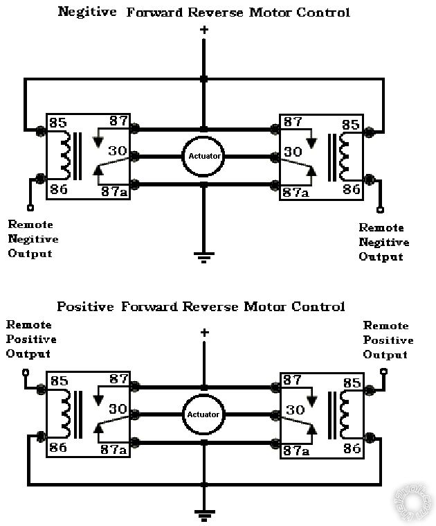
Posted By: davep.
Date Posted: June 01, 2015 at 12:32 PM
This is basically what you're doing with my above suggestion. You will have the two actuators in parallel:

Posted By: mjhinno
Date Posted: June 02, 2015 at 8:55 AM
Hey davep
HUGE thanks for taking the time to map this out. I understand completely and will wire a mock-up this weekend and let you know how it works out.
Posted By: hotwaterwizard
Date Posted: June 16, 2015 at 8:57 PM
 ------------- John DeRosa (Hotwaterwizard)
Stockton California
When in doubt, try it out !
Posted By: mjhinno
Date Posted: June 17, 2015 at 8:21 AM
Thanks hotwaterwizard. We were talking here about a negative switched circuit here too. Not sure which Ill use. Did not get to install this yet-kids graduation party, household stuff etc
|