Rear view camera automated screen.
Printed From: the12volt.com
Forum Name: Relays
Forum Discription: Relay Diagrams, SPDT Relays, SPST Relays, DPDT Relays, Latching Relays, etc.
URL: https://www.the12volt.com/installbay/forum_posts.asp?tid=139436
Printed Date: May 15, 2026 at 3:43 AM
Topic: Rear view camera automated screen.
Posted By: skylark-53
Subject: Rear view camera automated screen.
Date Posted: September 16, 2015 at 11:56 AM
I have a 1952 Chevy pickup (hot rod) and in the middle of the top of the dashboard, there's a "radio delete plate" (RDP for short).
I have hinged this RDP and attached it to the screen for the rear view camera. I want to use a cowl vent motor (7 rpm) to open the RDP whenever the back up lights are on and close the RDP whenever the back up lights are off.
For this to operate, I need to stop the RDP once the screen is the fully opened of fully closed position. I want to use micro-switches to stop the up or down travel but need help with the wiring of the relays and micro-switches to make this work.
Any help would be greatly appreciated.
Skylark-53
Replies:
Posted By: howie ll
Date Posted: September 16, 2015 at 12:57 PM
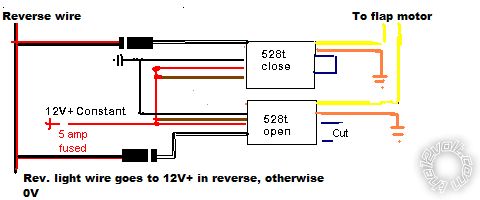
Here's a simple way to do this. Use the reverse (back-up) light feed.
This wire sits on ground, when reverse is engaged it goes to 12V+.
Use a pair of DEI 528t adjustable timer relays, just add 1/2 second to the normal open/close times, no microswitches required.
flap_motor.bmp------------- Amateurs assume, don't test and have problems; pros test first. I am not a free install service.
Read the installation manual, do a search here or online for your vehicle wiring before posting.
Posted By: skylark-53
Date Posted: September 17, 2015 at 7:55 AM
howie ll wrote:
Use a pair of DEI 528t adjustable timer relays, just add 1/2 second to the normal open/close times, no microswitches required.
flap_motor.bmp
Thank you for the quick response Howie II,
I found some of those timer relays online, they're a bit bulky for my installation. I was wondering if latching relays, or polarity reversing relays could be used instead... Also, the micro-switches would be on the motor bracket and I've already allowed for that (if need be).
Thanks again...
Skylark
Posted By: howie ll
Date Posted: September 17, 2015 at 7:58 AM
Then use normal relays and microswitches.
-------------
Amateurs assume, don't test and have problems; pros test first. I am not a free install service.
Read the installation manual, do a search here or online for your vehicle wiring before posting.
Posted By: skylark-53
Date Posted: September 17, 2015 at 8:54 AM
Howie, my knowledge on how to make that work is somewhat limited.
Could I ask you to read my steps below and sketch me a schematic, if it's not too much trouble.
These are the steps I "thought" could make this work with 2 relays, 2 micro-switches and 2 diodes:
Step 1 = Shifter moves into reverse gear
- Backup light circuit is activated
- NC relay OPENS (no current flows to the downward circuit)
- Diode also prevents flow to downward circuit.
- LED screen starts its upward travel.
Step 2 = LED screen reaches TOP of travel
- CW rotation trips NC micro-switch to NO and kills up upward circuit.
- LED screen now fully open for driver viewing.
Step 3 = Shifter moves out of reverse gear
- Backup light circuit closes
- Accessory side of ignition circuit powers downward circuit.
- NC relay from step 1 closes again.
- Second diode prevents current flow to the upward circuit.
- Motor polarity is now reversed.
- LED screen starts its downward travel.
Step 4 = LED screen reaches bottom of travel
- CCW rotation trips NC micro-switch at bottom of travel to NO and stops.
- Radio delete plate now completely closed.
Thank you for your time...
Skylark-53
p.s.: What program do you use to draw your schematics?
Posted By: howie ll
Date Posted: September 17, 2015 at 9:37 AM
Sorry, now you can see why I suggested the 528t, always use KISS principle, PAINT.
-------------
Amateurs assume, don't test and have problems; pros test first. I am not a free install service.
Read the installation manual, do a search here or online for your vehicle wiring before posting.
Posted By: skylark-53
Date Posted: September 17, 2015 at 12:36 PM
I understand Howie... Thanks anyway.
If I use Paint and design a schematic that I think would work, would you be willing to double check it for me?
Thanks again...
Skylark-53
Posted By: howie ll
Date Posted: September 17, 2015 at 12:44 PM
Of course.
-------------
Amateurs assume, don't test and have problems; pros test first. I am not a free install service.
Read the installation manual, do a search here or online for your vehicle wiring before posting.
|