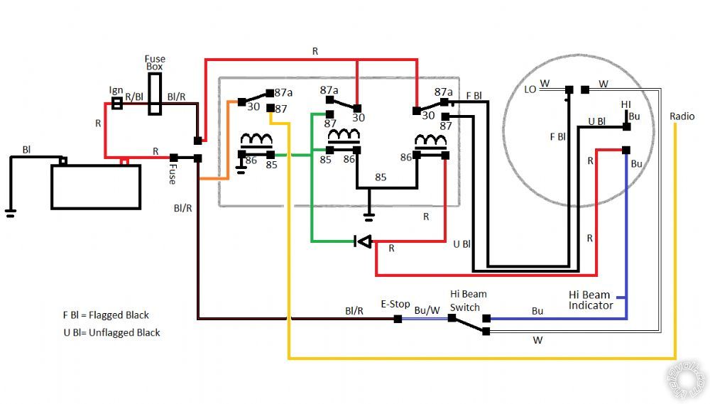
I am not sure if this belongs in the relay or motorcycle forum. If I picked the wrong one, feel free to move it. I just felt like it was more relay than motorcycle. I want my radio to come on when I flick the high beam switch. I want them to go off when I turn the bike off. I want it to come on, even with the bike off, when I hit the high beam switch. I chose the high beam switch as I didn't want to add another switch and wanted to keep it looking stock. Would someone please look at this wiring diagram and tell me if this looks like it'll work without any issues? I've tried to draw up my intent as clear as possible, but I'm fairly new to this. I'm sure I reinvented the wheel. If there's a cleaner way to do it, I'll take any advice.
Thanks.
-Elias
https://www.the12volt.com/relays/relaydiagram52.html
12volt constant output = wire to power your radio. Connection at bottom left goes to your high beam wire. Turn the high beams on and the relay will latch. It will not unlatch until voltage is removed from Accessory/Ignition wire.
Okay, I'm not sure why it took me so long to figure out that diagram. I had looked at it before I posted. I still have some questions. How can you get a diode placed between 85 and 86? Is it just a special relay? Looking at it, it seems like the diodes only purpose would be to keep the relay on the left from staying active with the right diode and backfeeding the momentary switch, whatever that is. In my post, I placed a diode to prevent a backfeed on the high beam light relay. Otherwise I'd have high beams on all the time after I flicked the switch..
What I really don't understand is what the purpose of the left relay is in the example. Why not just run the blue momentary wire into the right relay 87 with a diode? Doesn't that accomplish the same purpose? My only guess is that in the example, we might be dealing with a low power momentary on, but then that wouldn't activate the left relay either. So, after a few days of looking at this off and on I have come back to ask again..
In my example, the right diode turns on/off the high beams. The left diode has the radio powered off its own fused power, optional if the radio+hi-beam won't burn the fuse. My middle relay is meant to be a momentary+input to constant+output. I can swap it out for the two relay version depicted, if someone could please explain the difference, I'd appreciate it.
Thank you,
Elias
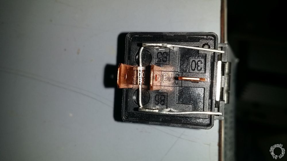
Solder the diode to the legs of the relay at the base of the leg so you can still slide a connector onto the leg.