I have an issue with my 2010 Chevy Pickup and I need a temporary but quick solution. I will try to be as clear as possible.
The AC compressor cycles on/off every few seconds. Its a $20 part that will require the dash being pulled out. (evaporator temp sensor). That is a project for another day.
So under the hood I can jumper relay pins 3 and 4 and run the compressor but that way it never cycles. Thats fine because right now its 95+ outside. At night, it may freeze up not being able to cycle on/off. Also at night even with the fast cycle it cools pretty good So I only want to jumper it during the day.
So I could make a toggle switch until I get the time to pull the dash and fix it. I have another idea though.
This truck has the mirror defroster and the relay to that is next to the AC relay. The thing about the mirror relay is that it times out after 10 mins or so. So if I were to forget to manually cycle the compressor it might freeze up. If I could use the mirror relay I would know pretty quick when it times out and hit the button again when I think it's time.
Basically I want to leave the AC relay in operation but also trip that replay from another relay if/when I want to manually operate the compressor. Sounds hokey but like I said its temporary and very hot right now.
Can someone tell me the best way for relay A to trip relay B?

The 10 minute time out is provided by the Body Control Module. It is not a part of the relay.
Thank you very much. Good detail and thats what I am looking for.
Yeah I know, really wasn't implying that but I guess it looked like I was.
Ween, on these relays pin 85 is diagonal from pin 30. So I went with that instead of 87 since 87 is the gate(?)
Results of 85 to 85 jumper. With the defrost switch (off) the compressor runs constant. Defrost switch (on) the compressor cycles indicating that the compressor relay is operating solo.
Im having trouble with the logic unless it's a polarity thing with pins 85/86.
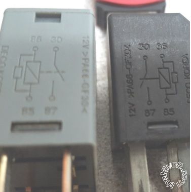
Do you have a multimeter? Place meter on ohms. Probe relay terminals. Two terminals should have around 80 ohms of resistance between them...these are the coil. The other two are the contacts. They should be diagonal sets, this way it doesn't matter how the relay is orientated in the fuse box.
Post a better pic of the relays, or inspect and see if terminal numbers are on the base...by the terminals.
Yep they where on the base. Works like it should. Thanks again I really appreciate your help.