Hello, I need to take a single wire and have it activate one of two different relays depending on polarity. For example a negative pulse would energise relay 1, a positive pulse would activate relay 2. Pulses would always be separate.
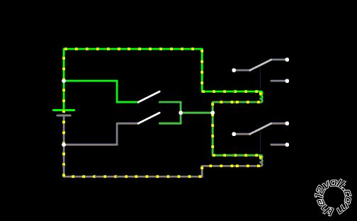
It is part of a larger circuit, but the rest I am confident with and I'm trying to keep this simple in the hope of some advice. The issue that I cannot overcome is how to connect the two relays without them bypassing the switch. Some variation of diodes may work but I am not sure. A quick diagram below, 12V automotive application.
If it can't be done I'd like to know also, thanks.
Are you wanting to latch the relays with the pulses or just activate them for the duration of the pulse?
The easiest way to activate your relays would be with opto-couplers (with inputs pins crossed over).
For now, only for the pulse duration. Not previously heard of optocouplers, how would they be integrated into a circuit such as above?
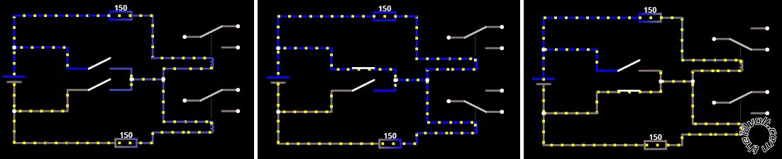
Suggested elsewhere was the use of two resistors at half the activation current of the relays. So current through both wouldn't be sufficient to activate, but one would. As drawn out below in it's three states. If done properly would this be reliable and consistent long term, without large current draw / burning out contacts etc?
mighty duc wrote:
For now, only for the pulse duration. Not previously heard of optocouplers, how would they be integrated into a circuit such as above?
Before detailing a solution using optocouplers, please clarify your meaning of positive and negative pulses.
Are you defining a positive pulse as starting at ground potential and then increasing to say +12V and a negative pulse as starting at +12V and then decreasing to ground potential?
Alternately are you meaning that your pulses are swinging between +12V and -12V?