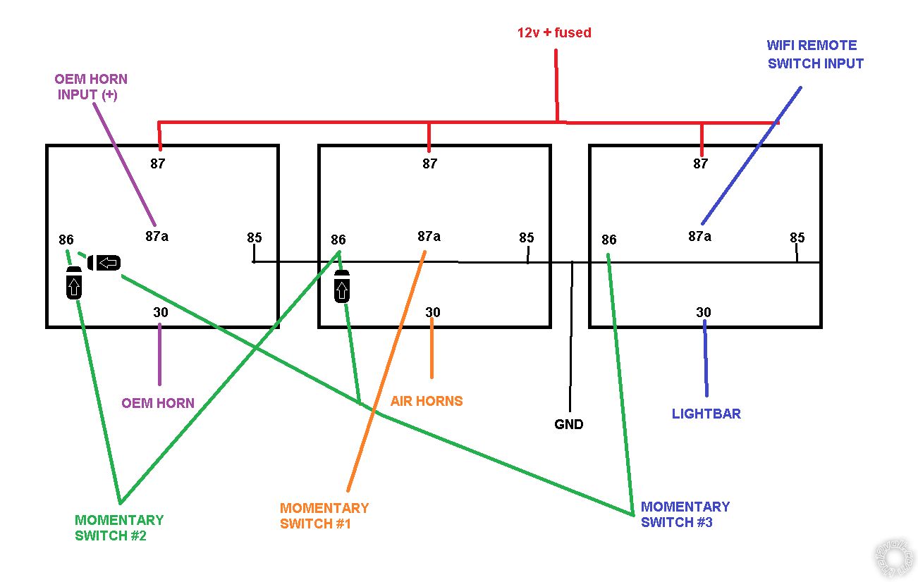
this post kind of goes in parallel with my previous post regarding "1 input 3 weak outputs"....so going along still with the diode diagram...i now want to be able to use 3 different momentary switches to have 3 different "levels/options" of my horn/lightbar setup. here's what i want to accomplish. my last setup i am going to completely redo so the 3way switch is also being removed
relay 1 oem horn
relay 2 aftermarket air horns
relay 3 top mounted lightbar
momentary switch 1 - honk only air horns
momentary switch 2 - honk air horns + oem horns
momentary switch 3 - honk both horns + flash top lightbar
does this setup w/ the diodes look correct? are 1a diodes strong enough to prevent power backfeed? which diagram is correct? it's been a while since i've done something custom like this. thanks in advance
Switch 1 directly to 86 of first relay.
Switch 2 directly to 86 of second relay.
Switch 3 directly to 86 of third relay.
Diodes from 86 on third relay to 86 of second relay. And from 86 of second relay to 86 of first relay.
Switch 1 will trigger relay 1. Switch 2 will trip relays 1 and 2. Switch 3 will trip all 3 relays.
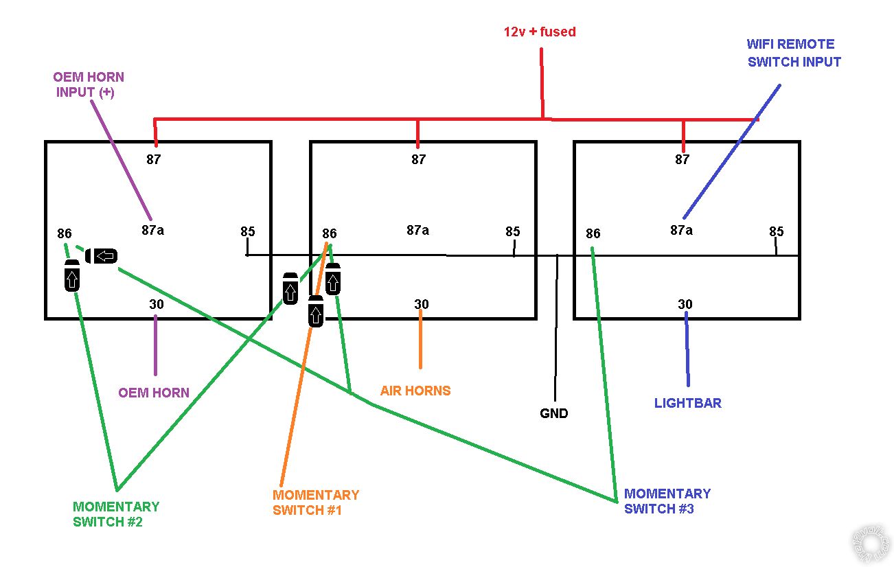
by doing that, is not going to accomplish the end result/goal. i get your diode explanation, but doing that, will still make Switch #1 only activate the OEM horn by itself. Switch #1 should be airhorns by themselves (which is why I connected to 87a instead). Switch #2 activates Air Horns + OEM Horn, Switch #3 activates both horns + lightbar.
Going off of what you recommended, I mocked up 2 new diagrams and put the relays in order so not to be confusing.
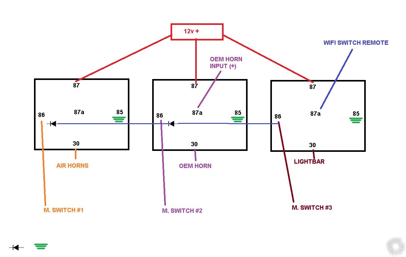
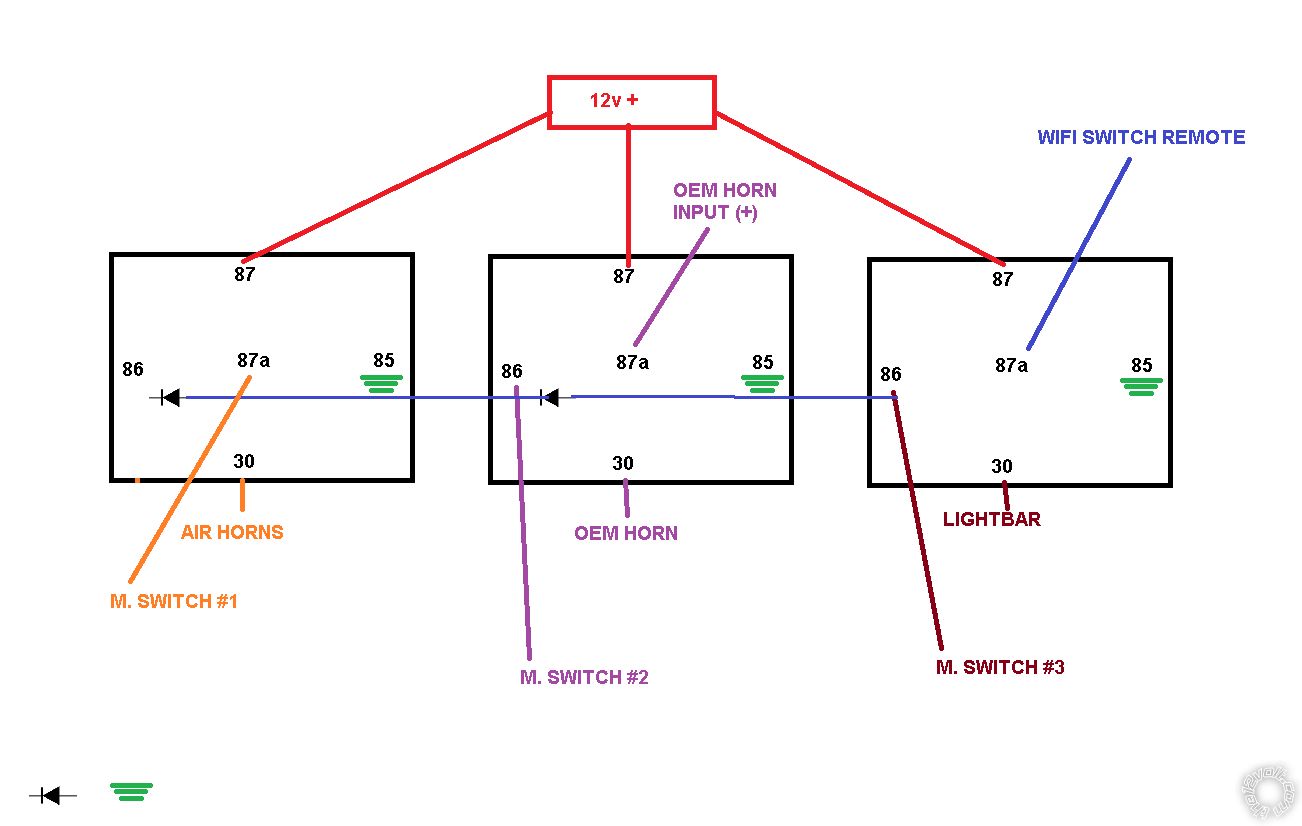
Top diagram will work exactly like you need. The bands are going the right way.
It would all be much easier to solve these simple problems if we could visualize the circuit as a real electrical schematic not as a physical wire placement view for automotive relays.
This going by terminal numbers on automotive relays is not helpful in understanding the electrical logic.
To answer your questions:
The 1A diode current rating is sufficient to drive the coils of several relays at the same time.
There is no current flow through the diodes in the reverse (backfeed) direction - so no worries there.
Get yourself 6 diodes connect the anode side of 1 diode to SW1, the anode side of 2 diodes to SW2, the anode side of 3 diodes to SW3.
Connect the cathode side of the diode for SW1 to Relay1 coil.
Connect the cathode sides of one of the diodes for SW2 to Relay 1 coil and the cathode side of the 2nd diode to Relay 2 coil.
You can probably guess at the SW3 diode connections.