My electronic fuel injection ECU has the capability of datalogging all engine functions for review at a later time. This is very useful for engine tuning, and the datalog feature can be triggered by a +12v or ground signal, either latched or momentary, from an external switch.
I also have my vehicle set up with a front brake line lock solenoid that is actuated by a momentary switch on the shift knob. Push and hold the button, the solenoid actuates and locks the front brakes. Instead of adding a separate switch just for the datalog feature, I want to use the existing momentary pushbutton switch as both a push-and-hold switch for the line lock, and also as a momentary switch to trigger the datalogger.
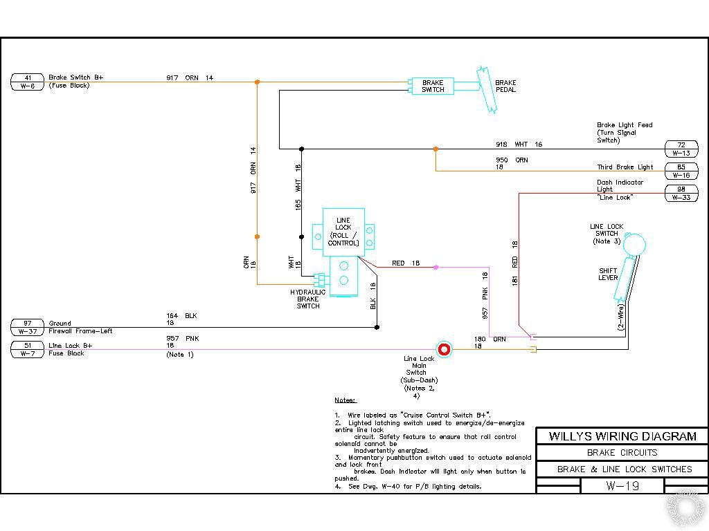
The first drawing is my current layout. I have an on-off pushbutton switch on the dash that I use to enable the line lock circuit. That switch is wired is series with the momentary pushbutton switch on the shift knob. If I want to engage the line lock, I close the dash switch, and then the line lock is engaged for as long as I push and hold the shift knob button.
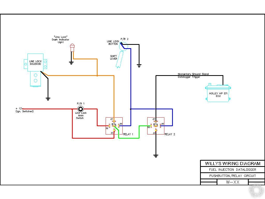
I figure that I can, with 2 relays, use the same switch on the shift knob to activate the line lock and also trigger the datalog feature. I know that this is either/or, and I dont plan on using both features at the same time. The second drawing shows the schematic for adding 2 relays to achieve this.
If P/B-1 is open, then the line lock feature is inoperative. Relay 2 gets power from the n/c 87a terminal of Relay 1. If I push P/B-2, I will create the momentary ground signal to allow datalogging by the ECU. If P/B-1 is closed and P/B-2 is pushed, the line lock solenoid is activated and power to Relay 2 is removed and the datalogger is disabled.
I would like opinions on this layout before I wire it up, and if there is an easier/better way of doing this, maybe 1 DPDT relay instead? The most important thing is that the ECU is completely isolated from the rest of the circuitry, with no chance of sending the wrong polarity pulse to the ECU.
Thanks for looking,
Steve
p.s. These drawings were converted from .dwg to .jpg. Formatting may be a little off, hopefully theyre still legible.