Relay or Diode Setup for Turn Signal and Brake Light
Printed From: the12volt.com
Forum Name: Relays
Forum Discription: Relay Diagrams, SPDT Relays, SPST Relays, DPDT Relays, Latching Relays, etc.
URL: https://www.the12volt.com/installbay/forum_posts.asp?tid=147316
Printed Date: January†10, 2026 at 4:24 AM
Topic: Relay or Diode Setup for Turn Signal and Brake Light
Posted By: coltmontana
Subject: Relay or Diode Setup for Turn Signal and Brake Light
Date Posted: April†10, 2022 at 8:13 PM
Good afternoon everyone. Let me start of by saying thank you to everyone on here. I have gotten tons of diagrams off this site over the years but never had to ask a question until now.
I have a 1980 c10 that I put a drag racing steering column in. When I did this I lost my turn signal switch and any correlating diodes/resistors/relays that controlled the turn signals/brake lights.
I have the wires below than went to the factory column
Light blue - L front
Blue - R front
Purple - power from fuse box
Yellow - L rear
Green - R rear
White - Brake
Brown - hazard
Black - horn
The truck has a factory two filament bulb with the standard ground on the socket. The new column has a 3 wire blinker switch with a positive, left, and right wire. I have connected all the wires to confirm that each wire is good and that the brake light switch works but when I wire them up the front turn signal lights up when I hit the brakes and the flasher stops flashing when the brakes are applied. How do I give the turn signal/hazards priority and wire it where the brake light only goes to the rear. Iíve been looking at a tail light converter but I donít see how this will work to give priority only split off the brake light signal to the front turn signal lights. I have diodes, 4 pin relays, and 5 pin relays on hand to work with or I can grab a tail light converter.
I did search on this forum and found a similar topic but it was discussing how to sync up the front and rear blinkers and didnt have a diagram for this specific situation.
Any help would be much appreciated.
-------------
Colt
Replies:
Posted By: coltmontana
Date Posted: April†10, 2022 at 8:15 PM

------------- Colt
Posted By: Ween
Date Posted: April†10, 2022 at 9:00 PM
You'll need 2 4-pin SPST relays and 2 5-pin SPDT relays...or 4 5-pin SPDT relays. Each side turn signals will use a SPST and a SPDT relay.
SPST relay contact wiring... 30 to front signal and dash indicator, 87 to flasher output.
SPDT relay contact wiring... 30 to rear signal/brake light, 87 to flasher output, 87A to brake light switch.
Relay coil wiring.. All 85 to ground. 86 of each sides relay to turn signal switch output for that side.
The turn signal switch selects which relays activate, which in turn operates the respective sides lights.
Brake switch connected to 87A (normally closed contact) allows brake lights to function normally.
When turn signal switch is activated, it removes the brake switch power, and connects to flasher.
Hazards if needed can be added.
Posted By: coltmontana
Date Posted: April†11, 2022 at 7:53 PM
Ween, Thank you so much for the help. This worked perfectly and was super simple to understand. I had tried three or four different ways and couldnít not get it right.
-------------
Colt
Posted By: Ween
Date Posted: April†11, 2022 at 8:03 PM
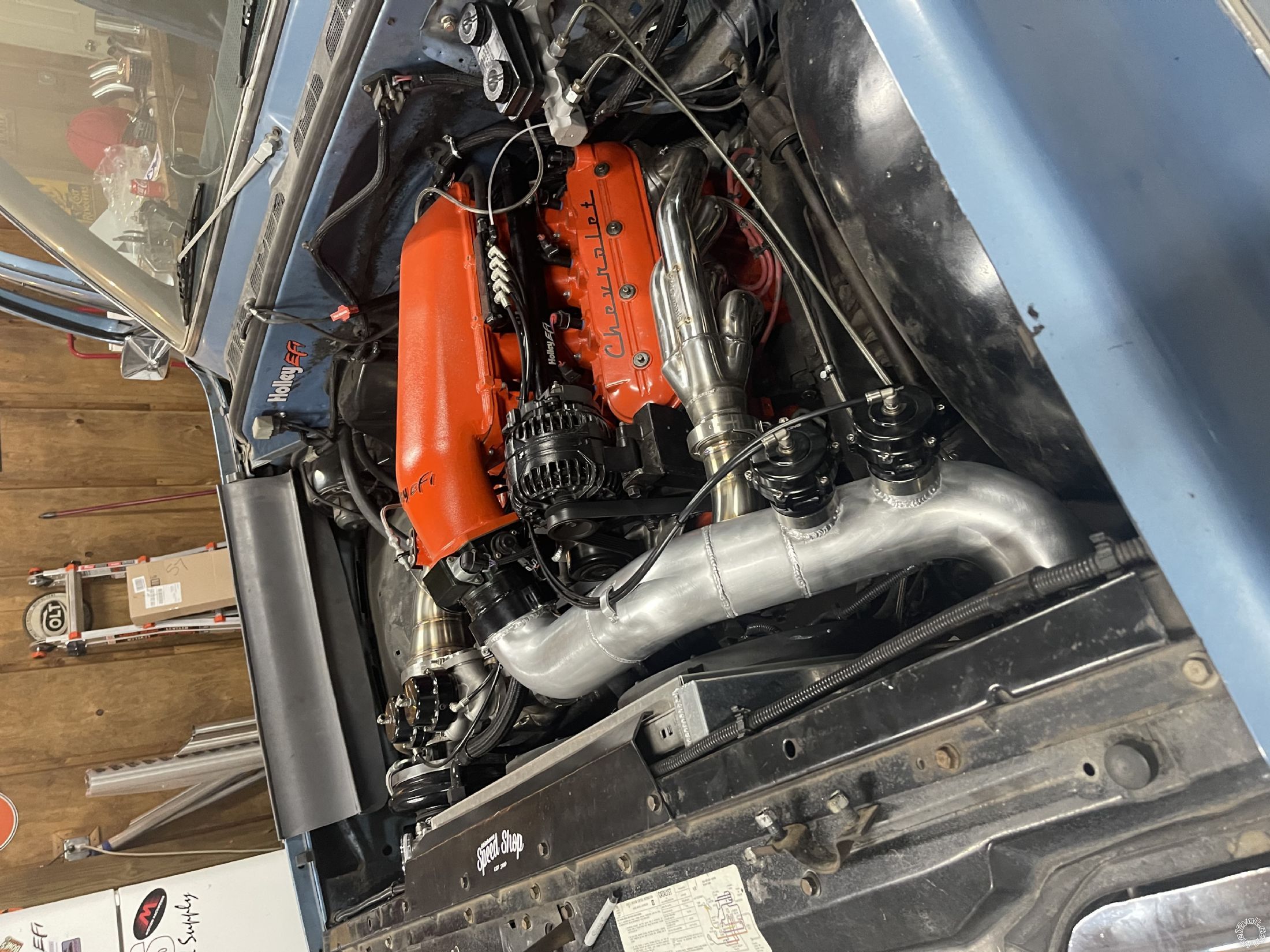
Cool! Glad to help, nice looking underhood. Might be fun to drive.
By the way, there's a few ways to do hazards. I'd use a 3PDT switch.
|
