A/C Cooling Fan Circuit For Dummies Like Me
Printed From: the12volt.com
Forum Name: Relays
Forum Discription: Relay Diagrams, SPDT Relays, SPST Relays, DPDT Relays, Latching Relays, etc.
URL: https://www.the12volt.com/installbay/forum_posts.asp?tid=147368
Printed Date: April 30, 2026 at 7:36 PM
Topic: A/C Cooling Fan Circuit For Dummies Like Me
Posted By: uh-1
Subject: A/C Cooling Fan Circuit For Dummies Like Me
Date Posted: May 24, 2022 at 6:48 PM
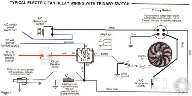
Folks, 1st post. I understand how a single relay works, but not the logic when employing 2 or more. I have a vehicle that uses a single electric radiator fan. It employs a single 40 amp relay which is triggered by +12 VDC signal from the engine ECU (Cummins R2.8 turbo diesel crate motor). By itself that works fine...but now the rub. I also need to find a method to trigger the radiator fan to come on when I turn on the A/C. The only diagrams I have been able to locate are based on signals to ground, not +positive , as that seems to be how all the thermostatic, binary and trinary pressure switches operate. When they reach their respective values, they all go to ground as the trigger for engaging A/C compressor and the radiator fan via a relay. So how do I incorporate a 2nd relay that will allow the ECU to call for cooling (turn the fan ON & OFF) when the engine needs it, yet still be able to turn the fan on when the A/C system is running? There will be times that the engine will not require cooling but the A/C system will. One of my concerns is feedback to the ECU, when both the ECU and the A/C system are requesting the radiator fan to turn simultaneously. I figure the 2nd relay would go where the manual override switch is in the diagram?
 ------------- Electrically challenged
Replies:
Posted By: Ween
Date Posted: May 25, 2022 at 5:51 PM
The trinary switch doesn't care if it switches positive or negative. So use a positive controlled relay circuit.
I would add a blocking diode (1N4000 series) in series with the PCM output, banded end towards fan relay.
This will isolate the PCM output from the trinary switch...keep 12Volts from backfeeding into PCM.
If you used a binary switch, wire an additional relay(coil)in parallel with the A/C compressor clutch. Also use
blocking diode on PCM. Have relay contacts supply power to fan relay coil.
Posted By: uh-1
Date Posted: May 27, 2022 at 4:05 PM
Thanks Ween, I'm still learning about this and appreciate the feedback.
-------------
Electrically challenged
Posted By: Ween
Date Posted: May 27, 2022 at 9:08 PM
Looks like a cool project. Did some surfing over on the Cummins site, what's the "swap" vehicle?
Posted By: uh-1
Date Posted: May 28, 2022 at 1:34 AM
Ween, it's a 1982 Jeep Wagoneer. 2 years in the making, down to the home stretch. When I get it on the road, I 'll post a link to see photos if you're interested?
-------------
Electrically challenged
Posted By: Ween
Date Posted: May 28, 2022 at 10:58 AM
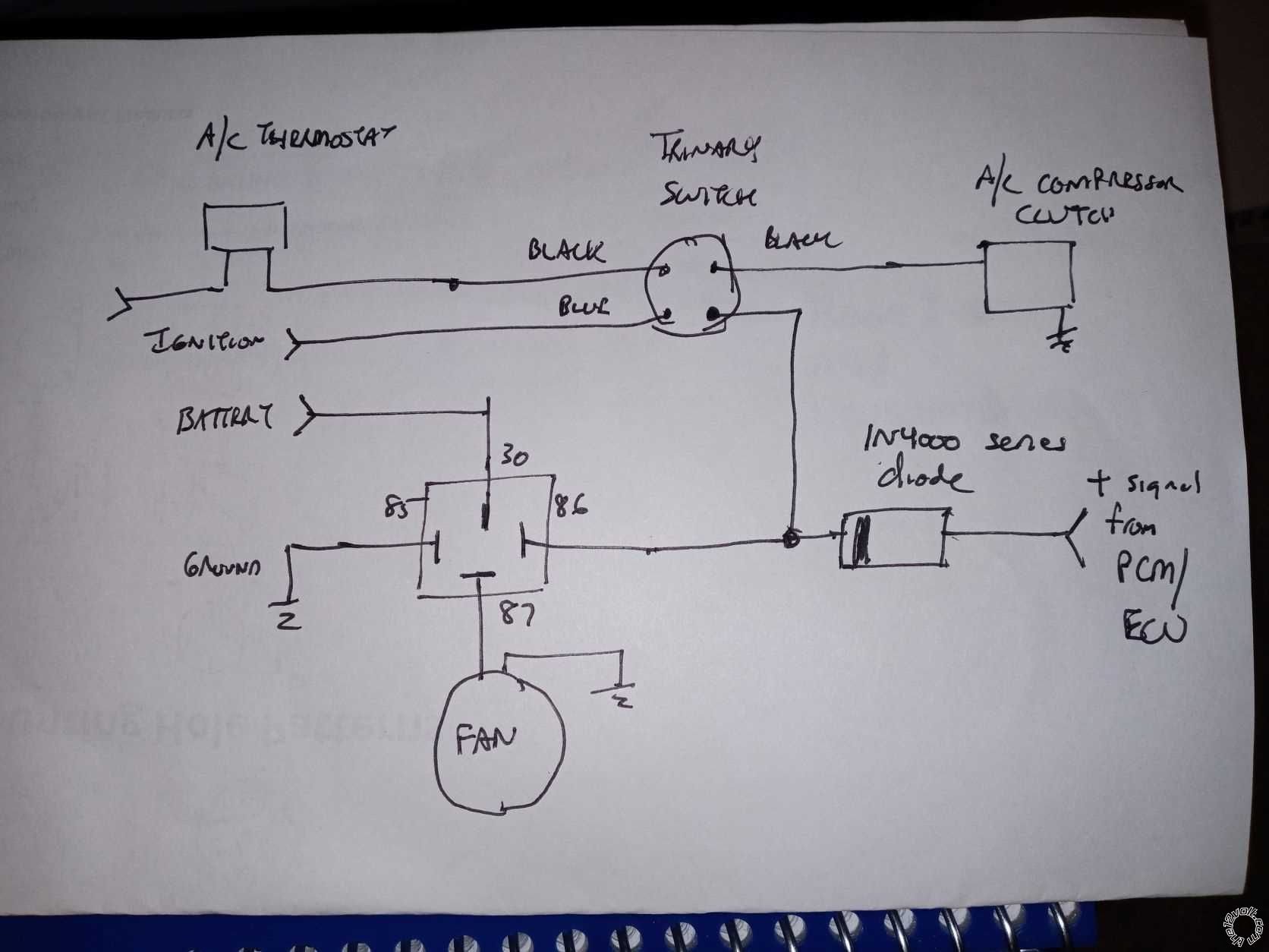 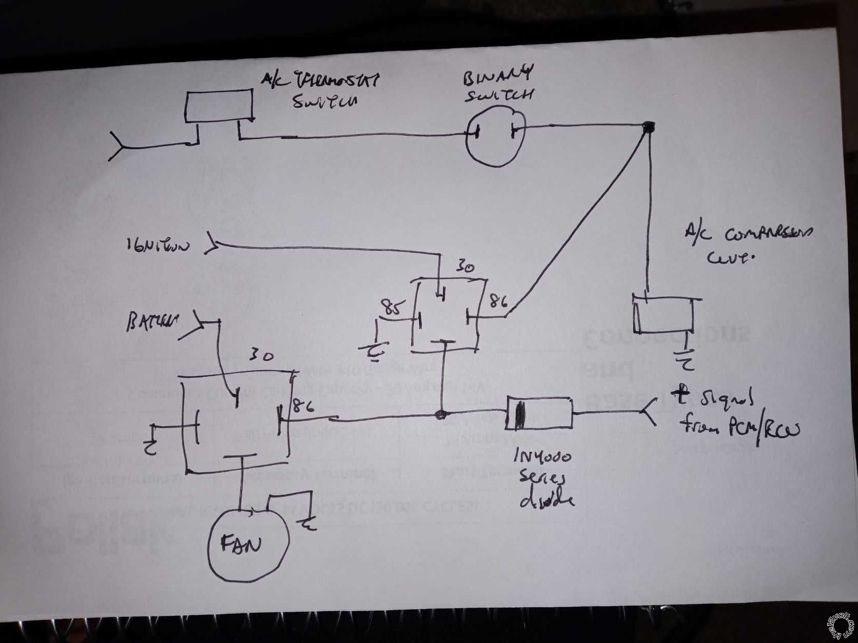
Some quick sketches of the trinary or binary switch wiring.
Posted By: uh-1
Date Posted: June 06, 2022 at 9:37 AM
Thanks again Ween, sorry for the delay, I was off-grid for 10 days. Your diagrams help me understand what is going on. I'll post when I finalize the install (or have more questions as to where I went wrong?)
-------------
Electrically challenged
|