Momentary to const question: for defrost
Printed From: the12volt.com
Forum Name: Relays
Forum Discription: Relay Diagrams, SPDT Relays, SPST Relays, DPDT Relays, Latching Relays, etc.
URL: https://www.the12volt.com/installbay/forum_posts.asp?tid=20087
Printed Date: February 02, 2026 at 4:19 PM
Topic: Momentary to const question: for defrost
Posted By: cpgoose
Subject: Momentary to const question: for defrost
Date Posted: October 14, 2003 at 12:55 PM
Hi,
I was researching on how to do this, but I'm a little confused. The alarm has an AUX output that's not being used, but it's only a 1/2 second long. I'd like to extend this to be constant so that they can turn on their rear defroster.
I guess I'm a little confused on how to turn this off. I'd like it to turn off say when they get in and turn the key, and hit the brake to change gear. So can I do it off of the brake's (+) wire? Do I need yet another relay to turn it off? Or maybe I can use the switched 12+ somehow?
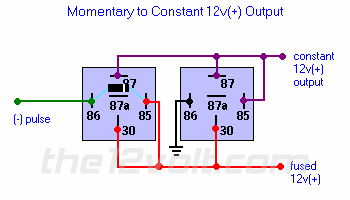
Here's the picture I'm talking about:

By the way, if you know what wire to use for the rear defroster in a '98 Sienna, that would be cool, too.
Thanks!!! ------------- Q: What's the best nation in the world?
A: Donation! Donate to the12volt.com
Replies:
Posted By: cpgoose
Date Posted: October 16, 2003 at 11:37 AM
If I use the accessory output of the remote start satellite (that I wasn't going to use) as my constant feed to the rear defroster, could I get this to work somehow?
Please help! I want the van out of garage!  ------------- Q: What's the best nation in the world?
A: Donation! Donate to the12volt.com
Posted By: the12volt
Date Posted: October 16, 2003 at 12:02 PM
To turn off the relay configuration above, you need to either break ground or interupt 12V+ to the second relay. If you use the accessory output of the remote start, there's no need for the relay configuration above to power the rear defroster, just one relay to provide enough current and/or change polarity of the output from the remote start. -------------  the12volt • Support the12volt.com the12volt • Support the12volt.com
Posted By: cpgoose
Date Posted: October 16, 2003 at 12:14 PM
Well, I was trying to make it so the remote's AUX channel could turn on the rear defroster while the car was remotely running. But since her remote does not have a latched output, I wasn't sure how to make her AUX channel keep the rear defroster running. In other words, I need a constant signal. I guess I was thinking I could use the ACC from the remote start to act as the constant signal, but I guess that's wrong.
Hmmm....if only the rear defroster button only needed a quick pulse, which would keep it on. If you hit the button in the car, it will turn on. But if you turn the ignition off and on again, the rear defrost button will be off again. Do you think if I gave it a quick pulse when the car was remotely running, that would act as if someone were hitting the button in the car?
Thanks for the help 12volt. It's nice to have a question answered after attempting to answer so many other ones.  ------------- Q: What's the best nation in the world?
A: Donation! Donate to the12volt.com
Posted By: xetmes
Date Posted: October 16, 2003 at 12:52 PM
i dont get it, does this vehice have a montary button to enable the defroster or is it some kind of latching switch, i think most are momentary because they switch off after a certain amount of time to prevent damage if turned on in hot weather. If it is momentary why not just go to the back of the switch and use the two sides of a relay to act as triggering the button, the same way you would if you pushed the button? If not you could use an SCR, once it recieves power (your aux output) it will remain on until it loses power.. i would favor the first idea much more though...
Posted By: cpgoose
Date Posted: October 16, 2003 at 12:59 PM
Yea, the vehicle has a momentary switch one like you described. I wasn't sure how to keep it on since the output of the alarm is only pulsed (1/2 second).
That would be awesome to use a relay to act like it's activating the switch...how do you wire that up? Don't you still need a constant signal (from the alarm) to keep the switch depressed....or do you just need a quick pulse, as if you're hitting the button on the dash. ------------- Q: What's the best nation in the world?
A: Donation! Donate to the12volt.com
Posted By: cpgoose
Date Posted: October 16, 2003 at 1:42 PM
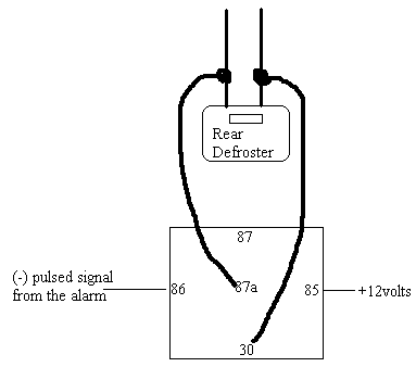
So can I do something like this?....assuming that the rear defroster has 2 wires. If it has more than that, how will I determine which 2 to use?
Thanks guys!
 ------------- Q: What's the best nation in the world?
A: Donation! Donate to the12volt.com
Posted By: xetmes
Date Posted: October 16, 2003 at 4:11 PM
yea thats what i mean assuming just 2 wires, pull the switch out and take a look, do some measurements with a meter to determine if that will work, always want to use the least invasive technique if it will work... also throw a diode on that coil 
Posted By: cpgoose
Date Posted: October 17, 2003 at 9:54 AM
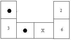
Ok, I got a couple of schematics from Toyota....hopefully this will help. Although I still can't really tell what the wire colors are by the fuse panel. But I think I got a schematic of the switch. Here's what it says:
2 - GROUND - Approximately 12volts with the ignition switch on
3 - GROUND - Always continuity
6 - GROUND - Continuity with the defogger switch ON and approximately 15 minutes thereafter
So can you tell from that which two wires I need to connect in order for the switch to turn on? Or do I just need to pulse power to #2. Hmmm, I don't think that's right, I think I need to connect two wires like you were saying.
Here's the diagram of the switch.

EDIT: Ok, I was able to get to the switch and the wiring behind it, and it looks just like the diagram provided (go figure:). So, do you think that when it says GROUND for those three wires, does that mean it rests at ground? And then with the Ignition switch on, (for position #2) it will show 12v+. So basically, I just need to give continuity between two wires, but I'm not sure which. ------------- Q: What's the best nation in the world?
A: Donation! Donate to the12volt.com
Posted By: xetmes
Date Posted: October 17, 2003 at 1:19 PM
is there a way you can disconnect the switch and measure to see what happens when it is pressed? The thing i dont understand is that you say "Continuity with the defogger switch ON and approximately 15 minutes thereafter" it stays at ground for 15 min then stops? thats how i am reading this... my assumption would be the switch causes 12V to 6, but thats purely a guess, i would really recommend removing the swich if possible and measuring what happens when pressed... does it look like it is just a button or does it appear to have some extra electronics with it?
Posted By: cpgoose
Date Posted: October 17, 2003 at 1:57 PM
Well, I got to the switch, and I'll be testing the wires tonight when I get home from work. Yea, that statement for #6 is confusing to me too. It says "continuity", but doesn't say what it's continuous with. I'm not sure if it gets ground or +12v. Again, I'll be testing the wires later on, but my only problem is that after I test them, I'll still be stuck 
Ok, here are the 3 sheets that Toyota sent me, and it's where I got the information for the previous post. Hopefully this will help somewhat...I'm not a schematic expert :-)
Page 01
Page 02
Page 03
------------- Q: What's the best nation in the world?
A: Donation! Donate to the12volt.com
Posted By: cpgoose
Date Posted: October 17, 2003 at 2:05 PM
For some reason, the pictures aren't linking correctly. you can copy and paste the link, and they should work. ------------- Q: What's the best nation in the world?
A: Donation! Donate to the12volt.com
Posted By: xetmes
Date Posted: October 17, 2003 at 7:34 PM
damn... it looks like they built the whole circuit into the switch... bummer, is the switch a large unit? possible to take apart at all? if you break it is it costly to replace? the diagram is pretty bad quality (first one) any way i can get a better quality version?
Posted By: cpgoose
Date Posted: October 17, 2003 at 7:42 PM
Well, I can try rescanning it, but I don't think it's going to come out much better. The one the guy sent me wasn't too good to begin with.
Well, there's a pushbutton for the defogger, and behind it is a decent-sized black box, so I'm sure there's a bunch of stuff built into it.
But the more I think about this (in theory), even if I figure out which wires to give continuity to in order to make the defogger work, won't I still need to give it a constant pulse to keep the relay energized? The alarm doesn't have a constant pulse, only momentary. If I'm going to have to wire up all of these relays and stuff, maybe this isn't worth it.
What do you think?? ------------- Q: What's the best nation in the world?
A: Donation! Donate to the12volt.com
Posted By: xetmes
Date Posted: October 17, 2003 at 7:55 PM
well by looking at that schematic my assumption is that it uses some sort of monostable timer (looks 555 based to me), the button itself does not keep the relay energized, the timer does, and the button triggers the timer, my idea was that the momentary could be used to trigger the timer, just like pressing the button (you dont hold the button down the whole time it is on..) All is not lost if you can get to the switch terminals, although i think that would be the best way. You could build a similar circuit and use it independent of the original...
Posted By: cpgoose
Date Posted: October 17, 2003 at 8:08 PM
Thanks for the quick reply.....I'm at home on a modem (slow as crap). That would be awesome if I could just give it a momentary pulse to mimic pushing the button, and giving 2 wires continuity. But I'm still not sure which wires are the correct ones to give it to.
Anywho, I did a preliminary check of the wires at the actual switch...and I used a (I know, I know) test light. I'll go try the multimeter right after I post this. Here's my findings so far (assuming the test light was showing 12v+ and ground):
WITH THE IGNITION ON AND THE SWITCH OFF:
Position #1: GREEN: (-)
Position #2: RED / BLUE: (+)
Position #3: WHITE/ BLACK: (-)
Position #4: WHITE/ GREEN: (-)
Position #5: EMPTY
Position #6: YELLOW /GREEN: (+)
WITH THE IGNITION ON AND THE SWITCH ON:
Position #1: GREEN: (-)
Position #2: RED / BLUE: (+)
Position #3: WHITE/ BLACK: (-)
Position #4: WHITE/ GREEN: (-)
Position #5: EMPTY
Position #6: YELLOW /GREEN: (-)
WITH THE IGNITION OFF AND THE SWITCH OFF:
Every position showed ground
------------- Q: What's the best nation in the world?
A: Donation! Donate to the12volt.com
Posted By: cpgoose
Date Posted: October 21, 2003 at 8:46 AM
Thanks for your help xetmes, but I gave up finally. Someone else told me that I may have to open the switch, and solder 2 wires to the board in there. That's when I had enough. I realized I was killing myself over something that they probably wouldn't use enough to warrant this much investigation. I hooked up her horn instead :-) Thanks again. ------------- Q: What's the best nation in the world?
A: Donation! Donate to the12volt.com
|


 the12volt •

