Alternating flashing lights?
Printed From: the12volt.com
Forum Name: Relays
Forum Discription: Relay Diagrams, SPDT Relays, SPST Relays, DPDT Relays, Latching Relays, etc.
URL: https://www.the12volt.com/installbay/forum_posts.asp?tid=22577
Printed Date: May 13, 2026 at 2:43 PM
Topic: Alternating flashing lights?
Posted By: pfitz
Subject: Alternating flashing lights?
Date Posted: December 08, 2003 at 9:40 PM
I am trying to figure out how I can make an alternating flash relay, the type used for wig-wag headlights. I know there is a bunch of companies that sell this type of relay!:errr: 1. I am too cheep to buy one.:oops: 2. I would probably ruin it taking it apart to see what makes it work (I do that alot!)}:) I want to use it with yellow lights on the back of my plow truck, I almost got smoked a few times today backing out of driveways that people could not see my roof light.:o): Thanks!
Replies:
Posted By: defective
Date Posted: December 08, 2003 at 10:17 PM
hmmm... probably something with a cap that would charge up after a second then dump and switch to the next relay, and soforth.....i'll have to have a coffee before i tackle this one.
-------------
Posted By: pfitz
Date Posted: December 09, 2003 at 9:10 PM
I was thinking that there might be a way with a standard signal light flashers and standard relays. All there is local is auto parts stores and a Radio Shack that doesn't even carry resistors anymore!
Posted By: markb
Date Posted: December 12, 2003 at 11:58 AM
how about something like this? 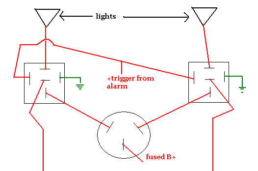 excuse my drawing skills.
Posted By: markb
Date Posted: December 12, 2003 at 11:59 AM
oh, the round thing is a signal flasher
Posted By: Teken
Date Posted: December 12, 2003 at 6:37 PM
LOL, great picture !!!
Regards
EVIL Teken . . .
Posted By: pfitz
Date Posted: December 12, 2003 at 7:08 PM
That is a real good drawing, but I don't have an alarm trigger (this could be a toggle swithc though I think) and it looks like the lights would flash at the same time like hazard lights. What I need is for them to flash at different times, back and forth? Let me know if this sounds right?
Posted By: mikeshonda750
Date Posted: December 13, 2003 at 6:10 PM
Im not sure if this setup will work and please excuese the size and crudeness. All i simply did was setup the relay to pulse a positive signal. This pulse can be changed by the size of the of capacitor to ground off of the relay. The 1st bulb pulses on, then moves to next capacitor, then flashes 2nd light. Please lemme know if this setup seems working. If i had a few bulbs and relays layin around the house i could have wired it up and tried a few thing... but this is the best i can come up with in my mind. 
-------------
Posted By: Teken
Date Posted: December 13, 2003 at 6:12 PM
LMAO... I almost went blind trying to view the image file. 
Posted By: mikeshonda750
Date Posted: December 13, 2003 at 6:13 PM
Omg the alltime noob post! Im sorry! Right click on it and click "save as" and it will open on your desktop normally. Again, i apologize for posting it like that and seeing how you cant edit... i cant fix it... If an admin would like... correct the post or delete it and post a link to the picture found at https://members.toast.net/mikeshonda750/image1.gir-------------
Posted By: mikeshonda750
Date Posted: December 13, 2003 at 6:17 PM
Posted By: the12volt
Date Posted: December 13, 2003 at 6:20 PM
Fixed your image on the previous page ;) -------------  the12volt Support the12volt.com the12volt Support the12volt.com
Posted By: pfitz
Date Posted: December 13, 2003 at 11:26 PM
What size capacitor would be used to have them blink fast, like when you have one light out on your signal lights?
Posted By: mikeshonda750
Date Posted: December 13, 2003 at 11:57 PM
Im not even 100% certain this setup will work... but as for pulse length's... it all depends. If it was me, i would make the ground pulse longer than the 2nd, and the 2nd bulb blink faster.... been a long ass time since i have worked with capacitors.. but i would guesstimate and say.... Ground= 2k and 2nd bulb 1k? this would give you probably a 1sec flash off of the 1st bulb and a faster flash off of the 2nd bulb. That is... if my diagram is functional and working... as for them alternating back and forth... on a timed circut.. i have been playing around with this in my head for hours and im not certain it would work at all either... will let you know if i come up with anything... -------------
Posted By: mikeshonda750
Date Posted: December 14, 2003 at 12:56 AM
In fear of posting another picture all messed up, i'll leave a link. https://members.toast.net/mikeshonda750/image2.jpg Pretty much.. the relay on the left sends a positive pulse to relay #2 via a capacitor of your choosing. Each light is tied to terminal 87 and 87a... so as the pulse is sent.. relay #2 opens and closes.... sending juice back and forth between the 2 bulbs. I wouldnt even begin to advise you on what size capacitor to use on relay #1 to ground. I would simply take a few bucks... head to radio shack... buy a few 12v bulbs.. relays... wiring.. a toggle switch and various sizes of capacitors(they should be fairly cheap) and wire up a demo type thing so you can make sure you get them flashing fast enough and dont burn up relays and such..... again.. this is just an idea i have been playing with in my head since i 1st read this post.... might work... might not... hoping others could go through my crude diagram and visually tell us (you) if it would function properly and not be too stressful on the relays and such.... dunno Good Luck! -------------
Posted By: -doh-
Date Posted: December 15, 2003 at 9:59 PM

this worked for me...
Posted By: Teken
Date Posted: December 16, 2003 at 10:32 PM
LMAO... I love the home made picture you guys make. 
Regards
EVIL Teken . . .
Posted By: hotwaterwizard
Date Posted: December 17, 2003 at 12:12 AM
Headlight Flasher This circuit was requested from an email. It will allow your car headlights to flash on and off at the same time or it will cause them to flash alternately. The circuit is based on the 555 timers. It is used in the astable mode. The 555-timer output will go high for an adjustable period of time and then turn off. It will then repeat the procedure. The time is adjusted by R1. To hook up the circuit to your car you must locate the positive wire from the fuse box to the headlights. Cut the wire and insert the relay contact and bypass switch. The bypass switch will allow you to bypass the relay contact for normal headlight operation. In the alternating headlight configuration you must cut the positive wire to each headlight and wire in the relay contact. 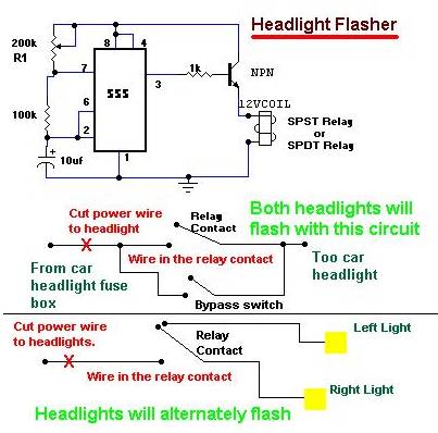
------------- John DeRosa (Hotwaterwizard)
Stockton California
When in doubt, try it out !
Posted By: pfitz
Date Posted: December 17, 2003 at 11:21 PM

this worked for me... |
Where or what does the red wire off the top of the first relay connect to? and is the 12v wire on the bottom from a switch or constant?
Posted By: NowYaKnow
Date Posted: December 18, 2003 at 5:53 AM
https://installz.com/wiringdiagrams/alternatingflash.gif
Posted By: Teken
Date Posted: December 18, 2003 at 9:42 PM
NowYaKnow,
That is an excellent example as to how to. In the schematic that I have, it uses a hi power rheostat, so as the flash rate can be controlled / varied.
Regards
EVIL Teken . . .
Posted By: pfitz
Date Posted: December 23, 2003 at 11:52 AM
I have tried what I thought were the easiest two of these ideas with no luck. I know how to wire...........that,s not the problem, it must be the parts that I am using. I have a 3 prong flasher for a Nissan...I think this is the weak link. What flasher should I be using?
Posted By: Teken
Date Posted: December 23, 2003 at 1:02 PM
There are two types of flashers I see currently the most.
1. The 552 is a two prong style. The schematic symbol (X) normally attatches to the relay. The (L) goes to the lights. This is used to flash only the parking lights, or one set of lights.
2. The 537 has three prong style. The schematic symbol (X) goes to the relay. (L) goes to the head lights. (P) Goes to the parking lights.
==============
Please refer to the above for discription, which is numbered 1 & 2
1) 30 = +12 VDC 15 amp fused
85 = Ground (-)
86 = Alarm output siren wire
87 = To flasher 552 of (X) and (L) is attatched to
the parking lights.
2) 30 = To flasher 537 of (X) pin
85 = Alarm siren output
86 = To +12 or GND depending upon alarm, etc
87 = +12 VDC constant 15 amp fused.
(L) would connect to the headlights (P) would connect to the parking lights.
This is just the standard method of connecting the flashers to the various light sources. Perhaps this will give you some insight to your problem.
Regards
EVIL Teken . . .
Posted By: NowYaKnow
Date Posted: December 23, 2003 at 8:33 PM
Not sure which diagram your trying, but don't feel bad I can't see how some of those diagrams would work anyway.  The main thing you need to make sure of is that there is a load off of the light output on the flasher. Running it directly to a relay or depending on what kind of light your using, it may not be enough to trigger the flasher. They want to see a low resistance.
What I do is get a 194 bulb and socket and wire it in as sort of a dummy load. Even some of the supposed "no load" flashers will not flash if there isn't some sort of expected load on it. To show you what I mean, here is an updated version of the diagram I drew up, to show how you would wire in the dummy bulb.
https://installz.com/wiringdiagrams/alternatingflash1.gif
As mentioned if you get the right flasher, you don't need to add this bulb. Even though the coil of the relay has probably around 90 - 150 ohms resistance, it isn't quite enough to make it trigger. Also what type of lights are you trying to alternate? As mentioned headlights normally are not isolated left and right so if you tap one, they are both going to come on so you'd need 2 relays to isolate the headlights first. Stay away from diode isolation here as you don't want to be dropping the voltage of your headlights any! Hope that helps,
Mike
Posted By: pfitz
Date Posted: December 23, 2003 at 9:51 PM
Mike, The toggle you have in the drawing, I am using a lit toggle with 3 terminals. Is the one you have supplying power or just to cut the ground?
Posted By: NowYaKnow
Date Posted: December 24, 2003 at 12:36 AM
Just to close/open the ground connection on the relay. If you wanted to use one of those lighted switches you would hook the ground to each side of the switch as normal and then give the remaining terminal 12v for it to light up. Last I saw those switches didn't care which way you hooked them up but you may want to double check. Meaning you could have the switch cut the positive and hook the ground to the lamp terminal, or you could have the switch cut the ground and hook the positive to the lamp terminal which would go along with my diagram better.
Mike
Posted By: dbrown
Date Posted: December 24, 2003 at 2:04 PM
NowYaKnow is right. Your average relay does not have enough current draw to trigger most flashers. In high school, I put these in to mine and a few of my buddies cars, and we'd pull our (gullable) friends over on the weekends. Anyway, I would basically use the flasher and relay setup, although instead of having a dummy light in the circut, I would simply use a resistor. In most applications, use a diode to prevent voltage flow back in to your BCM, etc. Unless you have an older vehicle, then it's cool to leave it out - that way the blue high beam indicator on your dash will flash when the circuit is active. Your best bet though (other than paying $40.00 for one at galls.com) is to employ a 555/556 timer, although it's a little more complex than using relays and flashers, but if you know what you're doing it's a lot more reliable and precise. Good luck.
-------------
Dig
Posted By: hotwaterwizard
Date Posted: December 24, 2003 at 8:10 PM
If you look on page 2 of this post you will find a diagram using a 555 timer.
-------------
John DeRosa (Hotwaterwizard)
Stockton California
When in doubt, try it out !
Posted By: pfitz
Date Posted: December 25, 2003 at 11:17 PM
I looked at the 555 timer listed on page 2, but the way it is broken into several parts is hard to follow. Any chance to make the drawing with more explination of what is hooking to what from part to part?
Posted By: black2nd12
Date Posted: December 29, 2003 at 11:22 PM
hey pfitz, i have exactly what you're looking for hooked up in my car right now. if you want the diagram email me @ deathsheartbreak@aol.com and i will be happy to send it to you.
Posted By: superchuckles
Date Posted: January 01, 2004 at 9:20 PM
heh - funny thing is, there are two bosch relays and a solid state circuit board in these, which makes them much more intricate than any simple two relays and a couple of capacitors. not to mention, they will flash at a regulated rate, over a very large range of voltage, whereas just using two relays and caps will make the whole thing vary depending on voltage. aaaaaaanyhow.... two bosch relays, a couple of capacitors, lets say that's all you are into it, and say you knew already just the right value caps to use. say you put the whole thing in a piece of heat shrink, or - maybe you put it in epoxy like they do. you're into it maybe $8 (being realistic.... and this is getting the relays cheap - on average, they sell locally for anywhere from $5 to $15 depending on how big of theives the autoparts/electronic supplier is) - maybe as much as $15? guess what - the entire thing is made by a company called Road Runner, and they're $15 brand new - and unless you add considerablly more solid state into your homemade than 2 relays and some caps, well, need i say more? $15 for professional setup, or - same amount for homemade that would be questionable to it's comparable quality/durability.
Posted By: superchuckles
Date Posted: January 01, 2004 at 9:33 PM
here's a quick pic of an old unit taken from a wrecked car - i would include the wiring diagram for these, but each one comes with a diagram in the box. 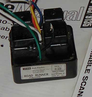
Posted By: pfitz
Date Posted: January 01, 2004 at 9:42 PM
Do you have a web link for them?
Posted By: NowYaKnow
Date Posted: January 01, 2004 at 10:30 PM
There's a ton of companies that make these. Try searching e-bay for "wig wag flasher" you should find a bunch.
Mike
Posted By: hotwaterwizard
Date Posted: January 02, 2004 at 10:14 AM
Wig Wag Flasher 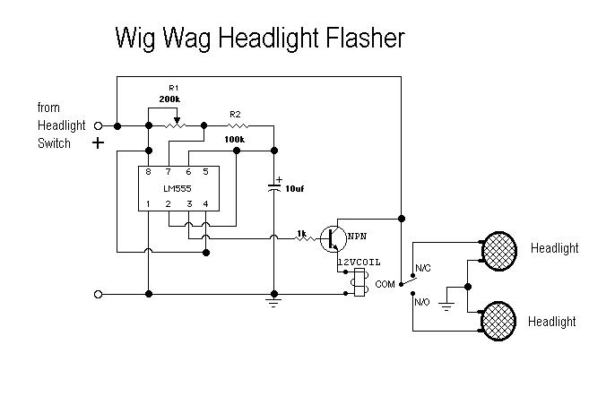 ------------- John DeRosa (Hotwaterwizard)
Stockton California
When in doubt, try it out !
|