Hi.
I've got a project in mind that requires a timed 30 second positive output from a momentary positive pulse. I know this can be done with a cap and a resistor to bleed the charge off slowly, but I don't know how to calculate cap and resistor values for a specific length of time.
Help?
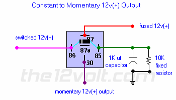
Hi Ugli, I have something that will help. While not a formula, the following diagram shows taking a constant output and switching it to a pusled output.
Using the same configuration, take a pusled output(+) and connect it to terminal 86 with the cathode side of a diode inline towards the relay. Connect terminal 86 directly to terminal 30. This will create a latch for as long as terminal 85 is showing ground after the relay coil has been energized. By increasing the size of the capacitor you'll increase the duration of the output. The resistor value should remain the same. If you need to do this with a negative trigger, simply use a relay to change polarity before connecting to terminal 86. The additional diode is only needed if you have other circuits on the same switch to prevent powering them during the delay.

In the above example, the 1K µfd capacitor = 1/2 second output. Experiment with larger values to get the desired duration. Let us know how it turns out.
the12volt
Hi...uh, The.
I had seen that diagram before around here and it's what I plan to use, but I was hoping for a better idea of what sized cap I may need to increase the timed duration to avoid having to buy a million different ones. Since, as you say, the above diagram yield about a half-second, can I assume that 30 seconds needs a 60k cap? If so, that sounds a little big... could I drop the resistor size to even things out or is there a specific reason you mentioned leaving the resistor value alone?
Maybe some more clear background will help: this circuit is for adding domelight supervision to an alarm that doesn't come with it (Viper 300)... I plan to use the positive door lock/unlock wires from the alarm (isolated, of course) to charge the cap when the alarm is turned on or off.
Thanks for the help so far.
-------------
