constructing a nand gate
Printed From: the12volt.com
Forum Name: Relays
Forum Discription: Relay Diagrams, SPDT Relays, SPST Relays, DPDT Relays, Latching Relays, etc.
URL: https://www.the12volt.com/installbay/forum_posts.asp?tid=25092
Printed Date: May 15, 2026 at 11:47 AM
Topic: constructing a nand gate
Posted By: model x
Subject: constructing a nand gate
Date Posted: January 22, 2004 at 7:24 PM
I have a honda crx that uses two wires for the turn signals and two for the brake lights and I want to convert it to 2 wires so that the brake lights signal my turns. I know a NAND gate would do this but I don't know how to construct one or if I can construct one using relays. What are my options?
Replies:
Posted By: xetmes
Date Posted: January 22, 2004 at 7:46 PM
this should perform the NAND function, you may want to add diodes its your call... 
Posted By: model x
Date Posted: January 25, 2004 at 9:49 PM
I don't think that'll work. IN-1 sends a 12v signal. Basically this is what the truth table would look like for what I need: X Y | output 0 0 0 0 1 Y 1 0 1 1 1 Y Where X is a 12v brake signal and Y is a 12v turn signal. The turn signal can also be viewed as a clock signal.
Posted By: JasonL
Date Posted: January 27, 2004 at 1:51 PM
The truth table you posted describes an OR gate. The schematic posted above also implements an OR gate (not a NAND)
The truth table for a NAND gate is:
X Y Out
0 0 1
0 1 1
1 0 1
1 1 0
Not exactly sure what you are trying to accomplish... you want the brake lights to come on when you signal a turn??? If I understand you correctly, you are going to need 3 inputs (brake, turn signal activated, and turn signal bulb) which makes the logic more complex.
Posted By: xetmes
Date Posted: January 27, 2004 at 4:19 PM
ohh man your right I drew the diagram wrong that common 12V on the coils is supposed to be ground.. ugh I dont know what I was thinking. I dont understand your truth table what are Y outputs?
Posted By: model x
Date Posted: January 27, 2004 at 7:44 PM
Ya when I was simplifing the logic I could use the NAND but for the circuit I need something that closely resembles an OR XY output 00 0 01 Y (just output whatever Y is, which would be the turnsignal) 10 1 (brake light signal) 11 Y (if I'm applying the brakes while signaling a turn I want to output the turn signal) Where Y is the turn signal output hopefully this is more clear. I just want my brake lights to signal my turns.
Posted By: JasonL
Date Posted: January 27, 2004 at 10:16 PM
A note about truth tables... when you write output=Y, Y is already defined as an input, thus it is a fixed value. This is pure combinational logic and each set of inputs will have one and only one output. What you have written above is the same as:
X Y Out
0 0 0
0 1 1 (because Y=1)
1 0 1
1 1 1 (because Y=1)
This will NOT accomplish what you want... because when you apply the brakes, the lights will not flash.
You will need a third logic input.
Let X = brakes applied
Let Y = turn signal activated
Let Z = turn signal bulb on (cycles between 0 and 1)
X Y Z Out
0 0 0 0 (brakes off, turn signal off)
0 0 1 0 (brakes off, turn signal off)
0 1 0 0 (brakes off, turn signal on)
0 1 1 1 (brakes off, turn signal on)
1 0 0 1 (brakes on, turn signal off)
1 0 1 1 (brakes on, turn signal off)
1 1 0 0 (brakes on, turn signal on)
1 1 1 1 (brakes on, turn signal on)
Does that make sense?
Posted By: JasonL
Date Posted: January 27, 2004 at 10:32 PM
OK, being an engineer I got a little carried away with the digital logic. Whoops :D
You might be able to simply use a SPDT relay.
85 - turn signal activated (probably need to run a wire near the steering column)
86 - gnd
87a- brake switch signal
87 - turn signal (output from the flasher)
30 - brake light bulb
You would need one relay for each side, and the 85 terminal only watches for the turn signal activation for that particular side (left or right).
Posted By: xetmes
Date Posted: January 28, 2004 at 5:26 AM
K-map it 
Posted By: model x
Date Posted: January 28, 2004 at 8:14 PM
Alrighty, Adding the third term makes way more sense; thanks JasonL. And I see what you mean for the spdt relay. All I need is to find a wire that has a constant 12v when I've initiated a turn signal. After ploting the k-map I get x(y)' + yz but I this still leaves me with the task of finding the constant 12V signal that's mentioned above. Well I can see the light now,
Posted By: JasonL
Date Posted: January 28, 2004 at 10:39 PM
model x wrote:
x(y)' + yz but I this still leaves me with the task of finding the constant 12V signal that's mentioned above.
If you think about it, that equation defines a SPDT relay 
If Y is true, select Z.
If Y is false, select X.
Anyways, I think you're going to have to dig up some factory wiring schematics to find the turn signal wires, unless you don't mind tracing wires in the steering column (doesn't sound fun). Or if you know the location of the turn signal flashers, that might be a start. Good luck.
Posted By: superchuckles
Date Posted: January 29, 2004 at 2:56 AM
talk about over complicating things...... could anyone possibly try to explain this in a more complicated method than has been done thus far? why is it that it cannot be simply stated (the goal) like saying, "my car uses seperate turn signal and brake light bulbs, and i would like to consolidate all the signals into a single output circuit for each side, how do i do this?" -- that was only an example, since i already know how to accomplish that circuit (and any other automotive circuit actually).... i'm just saying why not make it simple. a nand gate logic looks like this: 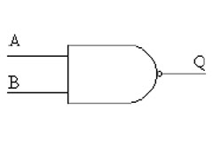
and it works like this: 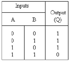
now, why you would want a light on when the input from both turn signals and brakes are zero is totally beyond me.... i'm guessing (because i have to due to the way your question was asked) that what you're really looking for is an XOR circuit ... which works like this: 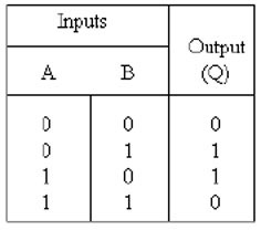
either of those should be pretty easy to make from relays, but it helps to know for sure which / what you need first.
Posted By: JasonL
Date Posted: January 29, 2004 at 2:34 PM
The XOR will not work. All he needs is a single SPDT relay per side like I mentioned.
And hey, some of us enjoy talking about circuits 
Posted By: model x
Date Posted: January 29, 2004 at 5:46 PM
Hey chuckles if you read the first post you might notice where I state what I want to acheive, "I have a honda crx that uses two wires for the turn signals and two for the brake lights and I want to convert it to 2 wires so that the brake lights signal my turns". If you already know how to solve my problem why have you not yet demonstrated it? even after the problem was already solved. I know that I just need the input wire for the flasher, so problem solved. thanks
Posted By: superchuckles
Date Posted: February 11, 2004 at 8:31 PM
firstly, the nand wouldn't work (because when the turn signal would be flashing, the light would just stay on if the brakes were on too - the xor would work, because it would still flash when the brakes were on and the turn signal on - read the logic) and - i have nothing against discussing circuits, that's why everyone is here.... it just makes it easier if you're clearer about what you want, because i can think of half a dozen ways to accomplish what you want to do, and i don't want to sit here and make a seperate schematic for each and every one - though i'm sure if you look at some of the other posts here, you will find your questions already been asked and answered long before you even posted your question. btw, a single spdt relay is one possible solution - and it may work ok, but - try pulling all the bulbs from your vehicle except for the actual tail lights themselves (i.e. simulate having the fronts blown) and see if the single relay still works. any permanent solution shouldn't rely on any other bulbs in the system to operate unless it's ok with you that one bulb blows and now you don't have turn signals
|