Goal = Interior lamp on until start’n car
Printed From: the12volt.com
Forum Name: Relays
Forum Discription: Relay Diagrams, SPDT Relays, SPST Relays, DPDT Relays, Latching Relays, etc.
URL: https://www.the12volt.com/installbay/forum_posts.asp?tid=39243
Printed Date: May 15, 2026 at 2:27 PM
Topic: Goal = Interior lamp on until start’n car
Posted By: sm951
Subject: Goal = Interior lamp on until start’n car
Date Posted: September 16, 2004 at 6:50 PM
Hi, I tried to do a search, but couldn't find clear information on this. I'm trying to have the interior dome lamp stay on once I open the door until I turn the key to the start the car. Then with the motor on and key in the "ON" position, the lamp should also turn on when a door is opened, but turn off immediately after the door is shut. With the motor off and the key in the "OFF" position, the lamp should stay on for a short period of time and then fade off by itself. Most of the newer cars' lamps function like this and it would be nice to get my car to do the same. Currently, it turns on and off with the opening and closing of the door. Thanks in advance for your help. This is a great site. Simpson
Replies:
Posted By: sm951
Date Posted: September 16, 2004 at 9:14 PM
I'm a newbie to all this, so work with me. Would this work, or am I WAY off?
Posted By: sm951
Date Posted: September 17, 2004 at 8:59 AM
Man, I just realized that diagram is WAY off.  Does anyone have a proven diagram? Thanks again...
Posted By: hotwaterwizard
Date Posted: September 18, 2004 at 10:31 PM
Here is one. 
------------- John DeRosa (Hotwaterwizard)
Stockton California
When in doubt, try it out !
Posted By: sm951
Date Posted: September 19, 2004 at 1:03 AM
hotwaterwizard wrote:
Here is one.
Thanks! But since I'm EE illiterate, could you please explain the elements of the diagrams in terms of a SPDT relay pinout - where they go and what they are? Thanks again...
Posted By: 5150azn
Date Posted: September 19, 2004 at 1:09 AM
Gorsh I'll be waiting for the reply on this one too. I'm usually really good with reading this stuff but it's been a while.
Good topic dude!
-------------
Tell the Snap-On guy I'm not here!
Posted By: hotwaterwizard
Date Posted: September 19, 2004 at 1:30 PM
You will need a Soldering Iron. 
------------- John DeRosa (Hotwaterwizard)
Stockton California
When in doubt, try it out !
Posted By: hotwaterwizard
Date Posted: September 19, 2004 at 1:40 PM
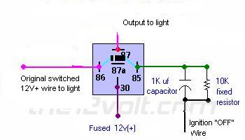
On second Thought here is an easier way to tie it in.  ------------- John DeRosa (Hotwaterwizard)
Stockton California
When in doubt, try it out !
Posted By: sm951
Date Posted: September 20, 2004 at 9:14 PM
Thanks John! A couple of questions: -what will energize the relay to give continuity between pins 87 and 30? -and I'm guessing if the ignition switch isn't in the "OFF" position, the capacitor will not get charged up?
Posted By: hotwaterwizard
Date Posted: September 20, 2004 at 10:11 PM
The Transistor conducts and sends a voltage to the Relay. As the capacitor discharges thru the Diode on pin 85 it slowly looses voltage until the Transistor finaly turns off and the Relay in turn shuts off too. ------------- John DeRosa (Hotwaterwizard)
Stockton California
When in doubt, try it out !
Posted By: hotwaterwizard
Date Posted: September 20, 2004 at 10:15 PM
Just remember I did not Design the Circuit I just modified it for the type of Relay you wanted it to use. I guess I need to Build a Test version of the circuit so I can see if the thing Actually works.
-------------
John DeRosa (Hotwaterwizard)
Stockton California
When in doubt, try it out !
Posted By: sm951
Date Posted: September 20, 2004 at 10:58 PM
hotwaterwizard wrote:
The Transistor conducts and sends a voltage to the Relay.
I see. So basically when current flows throw the wires leading to the light switch (pins 87 & 30), the Transistor activates the Relay?
Questions:
- What role does the lead going to the ignition switch and its Diode play? If it's to prevent the light from staying on when the key is not in the "OFF" position, how?
- How does the discharged current from the Capacitor "know" to go through pin 85 and not pin 86?
- Do pin 86, pin 85's Diode, and the Capacitor all get wired to the same ground? Thanks again for the EE education!
Posted By: hotwaterwizard
Date Posted: September 21, 2004 at 1:19 AM
Here is the original Text From Bills website. Power-Off Time Delay RelayThe two circuits below illustrate opening a relay contact a short time after the ignition or ligh switch is turned off. The capacitor is charged and the relay is closed when the voltage at the diode anode rises to +12 volts. The circuit on the left is a common collector or emitter follower and has the advantage of one less part since a resistor is not needed in series with the transistor base. However the voltage across the relay coil will be two diode drops less than the supply voltage, or about 11 volts for a 12.5 volt input. The common emitter configuration on the right offers the advantage of the full supply voltage across the load for most of the delay time, which makes the relay pull-in and drop-out voltages less of a concern but requires an extra resistor in series with transistor base. The common emitter (circuit on the right) is the better circuit since the series base resistor can be selected to obtain the desired delay time whereas the capacitor must be selected for the common collector (or an additional resistor used in parallel with the capacitor). The time delay for the common emitter will be approximately 3 time constants or 3*R*C. The capacitor/resistor values can be worked out from the relay coil current and transistor gain. For example a 120 ohm relay coil will draw 100 mA at 12 volts and assumming a transistor gain of 30, the base current will be 100/30 = 3 mA. The voltage across the resistor will be the supply voltage minus two diode drops or 12-1.4 = 10.6. The resistor value will be the voltage/current = 10.6/0.003 = 3533 or about 3.6K. The capacitor value for a 15 second delay will be 15/3R = 1327 uF. We can use a standard 1000 uF capacitor and increase the resistor proportionally to get 15 seconds. ------------- John DeRosa (Hotwaterwizard)
Stockton California
When in doubt, try it out !
|