OK. I wired up a relay (first time ever done) for the remote turn-on of my head unit to turn on 4 amplifiers. Anyway, I used a multimeter (when the cd player is on) and put the black probe to the chassis of the car, and the red probe on the barrier strip that I have distributing power to the 4 amps. The multimeter showed a reading of 0. Not sure if I have the relay wired up right, so could someone please refresh my memory as to what wires need to be connected to what terminals/posts of the relay?
Thanks much
Can you clarify what you are trying to do?
Most amps have a power terminal strip that has Power, Remote & Ground - the Power is always "HOT" and the Ground is always connected directly to chassis; then the remote input is fed from the remote "out" from the head & the power switching takes place inside the amp. No Relay shoudl be necessary.
However if you have amps that do not have an internal remote power switch then you will need to switch the current through a relay. See the information available directly on this site -
https://www.the12volt.com/relays/relays.asp
Specific application - https://www.the12volt.com/relays/page5.asp (connecting additional devices)
What power are your amps? i.e. How much current will they draw? You may need multiple relays with a sperate one for each amp - just wire them all up like the diagram above, connecting the common remote turn-on O/P from the head in parallel to teh 4 seperate relay coils (pin 86); then run the O/P from each pin 30 to the amp Power in.
Make sure you are using cable, relays & fuses that are all rated to meet your current demands. RRmember that if you common the power inputs to the pins 87, it will need to be sized to supply ALL the current for all the amps.
i know that. i have 4 amplifiers, which cannot be directly connected to the remote turn on wire of the head unit because it would draw too much current. therefore, a relay is necessary that is connected to the remote-turn on wire on the head unit and another part of the relay is connected to all the remote turn on wires of the 4 amplifiers. the other two posts/terminals on the relay are for 12v and ground. i just forget which wires go to which posts on the relay.
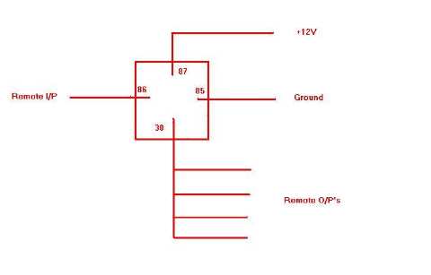
Remote I/P (from head) to coil, 86; 85 of coil to ground; 87 (N/O) to +12V; 30 (common) to the O/P bus for your 4 remote enables.
i don't see a picture. you have a link? thanks
Sorry - I have no idea why my pics aren't showing up - I'm new here and things are a little different from other forums! (e.g no edit until 50 posts!) The image shows up in the field when I upload it but not in preview or the final post. I followed the "sticky" instruction (or think I did!) but noseeums!
Anyway, just follow the text instruction for the pin wiring on the relay.
p.s. also sorry for initial confusion - I thought you were tryimng to do soemthing different when I read "the barrier strip that I have distributing power to the 4 amps".
hmm. a little strange. someone on another forum replied to the same topic, but said:
85 - remote wire from head unit
86 - ground
30 - 12 volt
87 - to amplifier remote turn-ons
crazymodgsr wrote:
hmm. a little strange. someone on another forum replied to the same topic, but said:
85 - remote wire from head unit
86 - ground
30 - 12 volt
87 - to amplifier remote turn-ons
Either is the same result:
86 - remote wire from head unit
85 - ground
87 - 12 volt
30 - to amplifier remote turn-ons
OR
85 - remote wire from head unit
86 - ground
30 - 12 volt
87 - to amplifier remote turn-ons
- as long as the "remote in" & ground are across the coil (85 & 86) and the 12v & O/P are across the N/O contacts (30 & 87) it doesn't matter which way round they are connected.
