I have been working (unsuccessfully) with the above setup, using the unlock pulse from my remote to turn on the courtesy and backup lights in my Tacoma. I added a third relay to break contact between 85 and 87 using the door trigger to open the 87a-30 contacts. That way the lights come on with the unlock pulse and then go off when the door is opened (except courtesy lights stay on until door is shut). Here are my questions.
#1 I had to add a fourth relay to convert the positive output to negative output.
Is there a way to do 'momentary to constant negative output' with fewer relays?
Also, when I add the 4th relay, I get problems with the latching not working. I need diodes added I'm sure but don't know where.
Could someone illustrate where the diodes go and maybe set up a diagram as I've tried to create? THANK YOU!!! :)
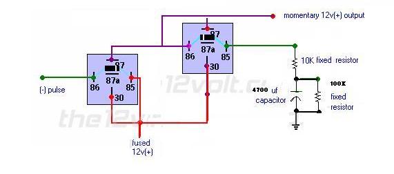
How about this?
This is a timer that will be triggered by your unlock pulse - should be good for ~ 30s or so (not sure exactly what voltage the relay will drop out at!) You can play with the R/C values a little to increase/decrease the time.
You'll still have to invert with another relay to get the -ve drive unfortunately, but you won'y have to worry about resetting - the 100K will discharge the cap.
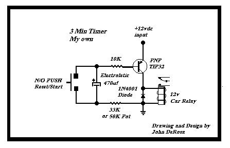
Has this timer circuit been tested?
It looks like the resistors and Capacitor will cause a voltage drop and the coil will not pull in the relay.
It is a Passive Timing circuit and there will be a voltage loss.
-------------
John DeRosa (Hotwaterwizard)
Stockton California
When in doubt, try it out !
The capacitor when discharged will keep the resistors from being a typical votage divider until the cap charges up via the RC time constant, when then it will turn off. That's the whole point, that the relay will turn off when the cap charges sufficiently to create insufficient voltage acorss the coil to keep the relay energized
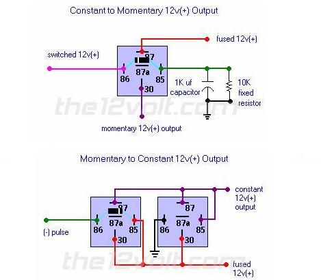
It's just a combination of these two relay circuits from the Relay: Special Application notes in the menu on the left, with some changes to the timing compnents:
https://www.the12volt.com/relays/page5.asp
.
I guess I need to hook this up and see if it actually works. Here is a circuit that has ben tested and works well. A smaller Capacitor will change the Timing.
-------------
John DeRosa (Hotwaterwizard)
Stockton California
When in doubt, try it out !
Here is how I would do it.
-------------
John DeRosa (Hotwaterwizard)
Stockton California
When in doubt, try it out !
I tried this circuit and it DOES NOT WORK
-------------
John DeRosa (Hotwaterwizard)
Stockton California
When in doubt, try it out !