I have a question that it seems i have figured out but would like to make sure that im right.
I'm installing an alarm system in manual it says:
Ground output when system is armed/remote started.This output os used for adding a starter disable relay or to activate AntiTheft Bypass modules for remote starting purposes.
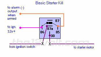
The farther description matches the diagram that is at this site in Relays -> Normally Closed Starter Kill Relay https://www.the12volt.com/relays/page2.asp . The question. Is this the correct diagram that i need in order to have Ground output when system is armed/remote started? The second diagram Normerly Open Starter kill relays on the ground from the alarm when disarmed. What is the difference between them?
Thank you!
The one that has the starter lead normally closed (shown below) relies on a negative output from the alarm when it is armed. The normally open diagram relies on a negative output from the alarm when it is disarmed (VSE alarms typically have this feature). According to your post your manual says your unit has an output when armed so you'll want to use the following diagram.

https://www.the12volt.com/relays/page2.asp#sk1
Quote:
Originally posted by the12volt on October 11, 2002
The one that has the starter lead normally closed (shown below) relies on a negative output from the alarm when it is armed. The normally open diagram relies on a negative output from the alarm when it is disarmed (VSE alarms typically have this feature). According to your post your manual says your unit has an output when armed so you'll want to use the following diagram.
https://www.the12volt.com/relays/page2.asp#sk1
Thank you. The description also matches.
Btw If I install shock sensor and dual microwave sensors to one Alarm input . Do I just isolate the output from sensors with 1amp diods and merge them into pre warn or trigger alarm input (as necessary) ?
Shock ---- diod ----alarm
|
Shock Micr. ---diod-/
Thanks!
Connect a diode to each sensor (-) output lead with the cathode side towards the sensor and connect each anode side to the alarm's (-) sensor input lead.
the12volt
