Switch controlling relay?
Printed From: the12volt.com
Forum Name: Relays
Forum Discription: Relay Diagrams, SPDT Relays, SPST Relays, DPDT Relays, Latching Relays, etc.
URL: https://www.the12volt.com/installbay/forum_posts.asp?tid=48855
Printed Date: May 06, 2026 at 11:59 AM
Topic: Switch controlling relay?
Posted By: slvr-bullet
Subject: Switch controlling relay?
Date Posted: January 29, 2005 at 4:40 AM
Hello all.
I'm kinda new to this site and am glad I found it 
Anyway, I purchased a push button switch but the problem is that it only completes the circuit if the button is held down. Once you release it, it opens the circuit. Is there any way to use an automotive relay with this type of switch so that when I push the button, it activates the relay and turns on my "accessories" and then when I push it again, it turns off my "accessories"?
The switch is similar to this but w/o the green ring.

Any other ideas is more than welcomed.
Replies:
Posted By: MJA1962
Date Posted: January 29, 2005 at 6:13 AM
https://www.the12volt.com/relays/page5.asp#mtc | Latched On/Off Output Using a Single Momentary Pulse | Similar to the momentary to constant configuration above, we can engage and disengage the latched output with a single pulse from a switch or an output from an alarm or remote keyless entry. The first pulse from the switch will engage the latch. The next pulse from the switch will disengage the latch.
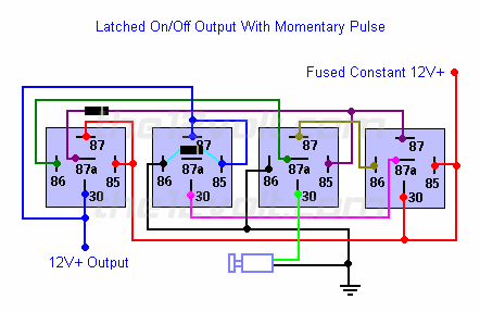
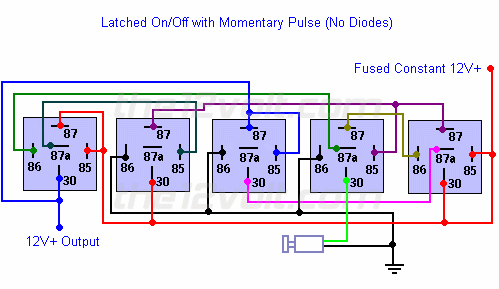
Here's the same configuration as the one above that you can use if you do not have any *diodes available and/or only want to use SPDT relays. A negative output from an alarm, remote keyless entry, or other device can be used in place of the switch shown in both of these diagrams.
 |
Posted By: slvr-bullet
Date Posted: January 30, 2005 at 2:11 AM
Thanx, you're the best 
Now, if I use either design will it interfere with audio cables (i.e. hum/noise)? This is going in to a location where I have no choice but to place it near audio cables 
Posted By: slvr-bullet
Date Posted: January 30, 2005 at 2:14 AM
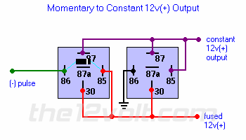
Forgot to ask also, can I not just use this design instead of using the 4-5 relays?
Momentary to Constant Output
Once activated by the relay on the left, the relay's coil on the right will stay energized until either ground or 12v(+) is removed. You can do this with another relay. Or try connecting to a 12v(+) switched source instead of a constant one. Or you can have a door trigger activate a relay to break continuity. The variations are practically endless.
Posted By: sneaky pete
Date Posted: January 30, 2005 at 10:02 AM
the latched on/off is probably what you want. the momentary to constant output will only turn on. you will need another switch to turn it off.
Posted By: sneaky pete
Date Posted: January 30, 2005 at 10:03 AM
the latched on/off is probably what you want. the momentary to constant output will only turn on. you will need another switch to turn it off.
Posted By: slvr-bullet
Date Posted: January 30, 2005 at 10:09 PM
Anyone know about this question??
slvr-bullet wrote:
Now, if I use either design will it interfere with audio cables (i.e. hum/noise)? This is going in to a location where I have no choice but to place it near audio cables
Also, my power source is 12VDC @ 500mA, what kind/type/rating of diode do I need?
Posted By: auex
Date Posted: January 30, 2005 at 10:23 PM
Will it interfere with audio cables, no more then anything else. I guess it would depend on how much current is going through this circuit. Also you have to use the first diagram posted.
-------------
Certified Security Specialist
Always check info with a digital multimeter.
I promise to be good.
Tell Darwin I sent you.
I've been sick lately, sorry I won't be on much.
Posted By: ff-mike
Date Posted: February 01, 2005 at 10:00 AM
Interference It should not interfere as this is a DC power circuit. Interference happens from changing current (AC or pulsating DC).
Diode Ratings[/b} You answered the question yourself when you stated 12C @ 500mA. Double it and you should be fine
Posted By: slvr-bullet
Date Posted: February 01, 2005 at 5:06 PM
ff-mike wrote:
Interference It should not interfere as this is a DC power circuit. Interference happens from changing current (AC or pulsating DC).
Diode Ratings[/b} You answered the question yourself when you stated 12C @ 500mA. Double it and you should be fine
I'm kinda illiterate when it comes to this stuff  What do you mean by "double it"?
Also, yes this is a DC power circuit but it will be residing near audio equipment that is powered by AC. Will it still be ok??
Posted By: ff-mike
Date Posted: February 01, 2005 at 5:48 PM
Double It 500mA * 2 = 1 Amp
Interference The DC should not cause problems with the AC. The AC may interfere with the DC, but the DC circuits in cars are usually filtered to remove alternator whine. If it does become an issue, just shoot another cheap filter in.
Posted By: slvr-bullet
Date Posted: February 01, 2005 at 6:08 PM
ff-mike wrote:
Double It 500mA * 2 = 1 Amp
Interference The DC should not cause problems with the AC. The AC may interfere with the DC, but the DC circuits in cars are usually filtered to remove alternator whine. If it does become an issue, just shoot another cheap filter in.
Thanks for the clarifiation on the doubling question
As for the intereference again, it's (the "DC circuit") actually going into a case where audio equipment will reside and the switch/relay configuarion is to turn on/off fans which will cool the equipment inside the case. That's why I want to make sure that the relays won't interfere with the audio because there's nothing like playing music to a crowd of people and suddenly "POP!!" when I push the button to turn on the fans.
Posted By: ff-mike
Date Posted: February 02, 2005 at 9:14 AM
The only way to truly find out is to try it. If there is a pop, turn on the fans first and then the music
|