reversing 12vdc polarity?
Printed From: the12volt.com
Forum Name: Relays
Forum Discription: Relay Diagrams, SPDT Relays, SPST Relays, DPDT Relays, Latching Relays, etc.
URL: https://www.the12volt.com/installbay/forum_posts.asp?tid=63631
Printed Date: May 14, 2026 at 9:45 AM
Topic: reversing 12vdc polarity?
Posted By: chrisp3
Subject: reversing 12vdc polarity?
Date Posted: October 02, 2005 at 10:02 AM
I found this site a couple of days ago and have found a wealth of info...thanks to all of you who take the time to post answers to great questions. Just figured out how to join and need some help. Can someone show me how to configure a relay or IC circuit that will allow me to press a SPDT momemtary rocker switch (integrated into the steering wheel) in one direction to apply voltage to an ALPS motorized volume control? When I press the button in the up postion i want the motor to rotate clockwise and when depressed in the other direction make the motor rotate in a counterclockwise direction? Right now....I am thinking that the black (common) wire at the switch is always going to carry - voltage and the + voltage is always going to be either the red or the yellow wires (the switch has three wires black (grnd), red (one side of the rocker) and yellow the other side of the rocker). Unfortunately in order for this to work I need to be able to flip the black wire from - to + whenever the switch gets depressed in one of the two mechanical positions.
Replies:
Posted By: fingaz22
Date Posted: October 02, 2005 at 11:24 AM
you can use a set like a power window operates. where the relays rest at ground and when one of the two relays are triggered on by the switch you desire(toggle)it will send a pos. polarity while the other relay stays at rest with gnd. and visa versa. sorry i am not set up yet to draw you a diagram. if you need i will explain indepth or mybe some one will jump in and have the pic. i would look for it in this forum on relays config.lol
-------------
JUST ONE MORE AMP!!!
hu,alpine cva 1005/dva 5205
sound processor,symmetry(first one).
sub amp,power 1000 the terminator.(1992).
subs,spl comp dual 1 ohms.
punch 150hd on a 10" ev.
alotofhighs
Posted By: boulderguy
Date Posted: October 02, 2005 at 11:30 AM
From the sound of it the switch won't offer different polarity to different wires, but will energize one of the two at any given time. You can route + thru the switch & then route each output to a seperate relay configured to send either pos or neg to the motor you control. Check here for relay configurations - https://www.the12volt.com/relays/page1.asp (there are actually 5 pages on this stuff).
Posted By: chrisp3
Date Posted: October 02, 2005 at 4:10 PM
Ok! Thanks for your responses! Since this a.m. I have done some research and come up with the following schematic. I am not the best artist but maybe someone out there can take a look at this and tell me whether it will work. Thanks Chris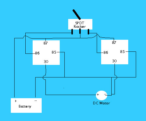
Posted By: boulderguy
Date Posted: October 02, 2005 at 5:24 PM
Nope, ain't gonna work, you've got a direct short on 30 on second relay. If the left relay is relay "A" and the other is relay "B," wire like this: relay A : 85 switched +, 86 ground, 87 constant +, 30+ to motor + terminal Relay B : 85 switched + AND to negative motor terminal, 86 & 87 ground, 30 neg out to positive motor terminal, 87a neg out to neg motor terminal (this gives the motor a ground when this relay isn't in use, otherwise when activated we're reversing the polarity to the motor to reverse it's motion). That should do it, or blow up your car. Either way, problem solved.
Posted By: boulderguy
Date Posted: October 02, 2005 at 5:27 PM
Or easier option, get a different switch with different outputs & eliminate the relays altogether. The above option assumes the switch can handle the current draw of the motor, in which case you could really eliminate one of the relays anyway.
Posted By: chrisp3
Date Posted: October 02, 2005 at 5:36 PM
Thanks boulderguy: I appreciate your taking time to look at my drawing....and now that you point it out, I see my short. The motor is a very small 50K motor that is attached to a potentiometer so I don't think anything will get burnt fried or otherwise damaged. The switch is an integrated switch that comes from a german car....and of course there is no drop in replacement for that could function as a DPDT switch. So....I am stuck trying to do the relay thing. I'll give this a try tomorrow and let you know how it works...or doesn't. Thanks again Chris
Posted By: boulderguy
Date Posted: October 02, 2005 at 5:40 PM
No problem, I like trying to figure relays out. If you're gonna do this, just go ahead & cut out relay A & run the positive switch direct to the motor positive. Be sure to fuse the whole setup.
Posted By: chrisp3
Date Posted: October 02, 2005 at 5:42 PM
Will Do! I'll send you a pm sometime tomorrow. Thanks again
Posted By: boulderguy
Date Posted: October 03, 2005 at 4:36 PM
Hey, had another thought - when you activate the second relay (really the only relay that needs to be there) it will have to cut the 87a at-rest ground before the switched positive reaches the motor. I'm thinking there will be a short for a fraction of a sec before the relay switches, but not sure. I'm gonna PM someone with more wisdom to look at it.
Posted By: chrisp3
Date Posted: October 03, 2005 at 4:40 PM
Thanks. I just got in...Haven't had a chance to do any testing yet....but am going to put it all together this evening.
|