paddle shifters for automatic solved
Printed From: the12volt.com
Forum Name: Relays
Forum Discription: Relay Diagrams, SPDT Relays, SPST Relays, DPDT Relays, Latching Relays, etc.
URL: https://www.the12volt.com/installbay/forum_posts.asp?tid=70221
Printed Date: February 11, 2026 at 9:23 AM
Topic: paddle shifters for automatic solved
Posted By: odecious
Subject: paddle shifters for automatic solved
Date Posted: January 07, 2006 at 1:06 AM
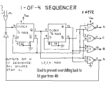
First a safety tip//...next i will show you how to shift down... 
Replies:
Posted By: odecious
Date Posted: January 07, 2006 at 1:26 AM
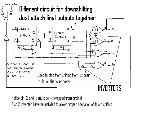
I believe this is a pretty good layout please tell me if you like it 2 different circuits used for upshifting and downshifting, but tie together at a,b,c,d took me about 2 hours to work all thing out and another to draw the safety now goes on the 1st gear to stop from shifting to 4th at the red light.
Posted By: odecious
Date Posted: January 07, 2006 at 1:28 AM
odecious wrote:
https://www.the12volt.com/installbay/forum_posts.asp?tid=40671&PN=1&tpn=2 orginal post First a safety tip//...next i will show you how to shift down... 
Posted By: hotwaterwizard
Date Posted: January 07, 2006 at 3:39 PM
Have you actually hooked up the circuit to see if it actually works?
-------------
John DeRosa (Hotwaterwizard)
Stockton California
When in doubt, try it out !
Posted By: odecious
Date Posted: January 07, 2006 at 4:02 PM
no i haven't made a live circuit with this set up, but theortically it will work if you dont understand any of the concept just ask i will explain
Posted By: hotwaterwizard
Date Posted: January 07, 2006 at 6:23 PM
You do realize that you have just complicated the circuit so it now uses 4 IC's. The OR on the input The Flip-Flops The NOR Gates and The Inverters I am working out the New Circuit Here is what I have so far. 
------------- John DeRosa (Hotwaterwizard)
Stockton California
When in doubt, try it out !
Posted By: odecious
Date Posted: January 07, 2006 at 10:38 PM
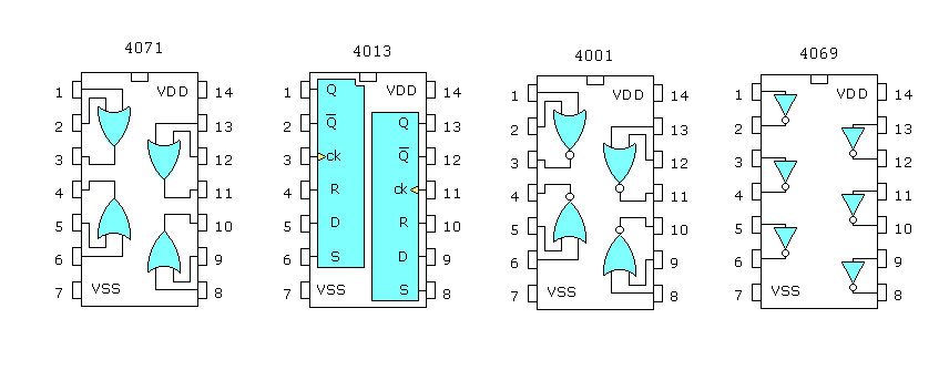
you actually must have 6 ic's all together up and down ic will be up must have 1 OR(1/4 chip), 2 Flip Flops(1 chip), 4 NOR's(1 chip), and 0 inverters down must have 1 OR(1/4 chip),2 Flip Flops(1 chip), 4 NOR's(1 chip), and 2 inverters(1/3 chip) by these terms you can use 1(4071 chip), 2(4013 chips) 2(4001 chips) and 1(4069 chip) you can not use the same flip flop or nor gate chips due to high/low conflict "which low generally wins" i would draw it if you would like.
Posted By: odecious
Date Posted: January 07, 2006 at 10:42 PM
sorry on the up circuit you need 1 inverter on the safety loop but the same 4069 can be used and also one extra on the down circuit for the same reason nonetheless you can use the same 4069 for the whole circuit total of 4 inverters
Posted By: hotwaterwizard
Date Posted: January 08, 2006 at 12:52 AM
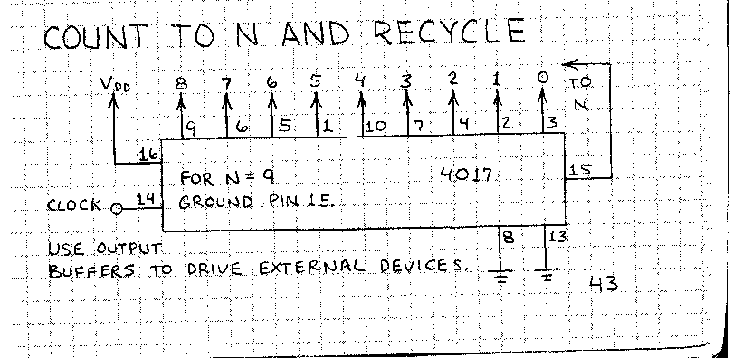
Here is an easier solution 
------------- John DeRosa (Hotwaterwizard)
Stockton California
When in doubt, try it out !
Posted By: KPierson
Date Posted: January 08, 2006 at 2:03 AM
In the two hours it took you to think that up I could have programmed a microcontroller to acomplish what you are going after, but with only ONE chip total. It actually sounds like a fun project, let me know if you would like my help. I could easily have it programmed, tested, and shipped within a few days. ------------- Kevin Pierson
Posted By: odecious
Date Posted: January 08, 2006 at 5:54 PM
well, i think you should have been the one to do it then...the point is i was pulling from another post that ask how to do it... i may not have the best information, considering im new with it, but i did get it done its not what you can/will do, but what you have done.
Posted By: hotwaterwizard
Date Posted: January 08, 2006 at 6:25 PM
You sure did get it done. You are alot like me. I love a challange. ------------- John DeRosa (Hotwaterwizard)
Stockton California
When in doubt, try it out !
Posted By: KPierson
Date Posted: January 09, 2006 at 12:29 AM
I see, I thought you were the original poster of that thread reporting back, I didn't realize you were just trying to solve it. However, technically you didn't solve the question, if I remember right, because the original poster wanted to use all relays!!! I would much rather use a system like you posted (or other chip based system) over relays any day. ------------- Kevin Pierson
Posted By: odecious
Date Posted: January 09, 2006 at 6:14 AM
KPierson, are you a electronic engineer? if so please help... I have a question concerning my next career progression options... Im in the US Army by the way i recently went to the DOD Medical Maintenance Repair Course which was 10 months of electrical tech. troubleshooting, both theoreticly and hands on. This course allows me to have 70 Semester Hours of College almost anywhere and i plan to use it. Should i get a Bachelor's Electrical Engineer or a Bachelor's Electrical and Computer Engineer Degree...Please explain. I also plan to progress to Master's Degree of the same field i just dont want to get headed in the wrong direction.
Posted By: odecious
Date Posted: January 09, 2006 at 6:16 AM
thanks for the help if any
Posted By: KPierson
Date Posted: January 09, 2006 at 7:07 AM
It all depends on what you want to do. My degree is in electronics and computer technology, not engineering. At the present moment I am an electronic field technician in the oil industry. I've personally always been a hands on type of person so an engineering degree wasn't a good fit for me. However, having the computer programming aspect of my education enabled me to start my own business. Every product we sell is based around programming, and would have been much more difficult had I not been introduced to the programming side of stuff in college. If I were in your shoes (which I'm not, so its hard for me to give you advice) I would go with the electrical and computer engineering option. This post is an example why. An electrical engineer can design a circuit to acomplish a specified goal using X amount of chips. A electronics and computer guy can design and build the same circuit using one custom programmed chip, and at the end of the day will most likely have more features, be more reliable, and be cheaper and easyier to manufacture. For what its worth, one of the guys I work with in the field got his electronics training in the US Army. He has no formal college education at all, just his military background. Its definately a good place to start. ------------- Kevin Pierson
Posted By: hotwaterwizard
Date Posted: January 09, 2006 at 11:42 PM
I was in the US Air Force. Avionics Systems Specialist. Navigations, Communications, Electronic Warfare, Ect. I worked on the Electronics on F15 Fighters. Troubleshooting The systems in the Aircraft. But, I don't claim to know more than anyone else. I have experience troubleshooting but not Engineering. You know the difference between Knowledge and Wisdom? Knowledge is knowing how to do something .You learn thru study and education. Wisdom is knowing what not to do with the Knowledge. You gain wisdom from your misteaks and you go beyond Knowledge into being wise. ------------- John DeRosa (Hotwaterwizard)
Stockton California
When in doubt, try it out !
|


