Alternating horns
Printed From: the12volt.com
Forum Name: Relays
Forum Discription: Relay Diagrams, SPDT Relays, SPST Relays, DPDT Relays, Latching Relays, etc.
URL: https://www.the12volt.com/installbay/forum_posts.asp?tid=76824
Printed Date: March 28, 2026 at 4:15 PM
Topic: Alternating horns
Posted By: rajkovic
Subject: Alternating horns
Date Posted: April 26, 2006 at 10:59 AM
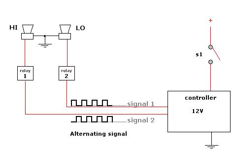
Hello! I'm making old euro-type siren (HI-LO) from auto-horns. They have two different frequencys. I want to hook up one relay for each horn on controller. 1. I need wiring diagram for controller.. any suggestion? 2. Can I hook up just one alternating relay on NE555 oscillator? 3. I need to know how strong is the trigger current on standard auto relay. Is it 200 mA? Thanks, Samo
Replies:
Posted By: rajkovic
Date Posted: April 26, 2006 at 11:19 AM
Posted By: rajkovic
Date Posted: April 26, 2006 at 2:49 PM
Could this wiring work!?  Just need a quick check of the diagram, which I draw.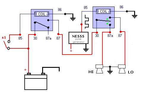 Thanks, Samo
Posted By: hotwaterwizard
Date Posted: April 26, 2006 at 11:17 PM
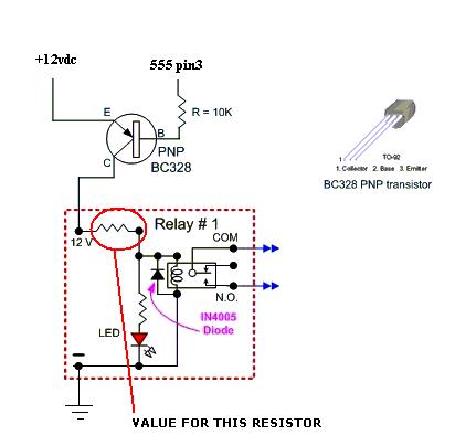
A simple relay controller with transistors would work as well. 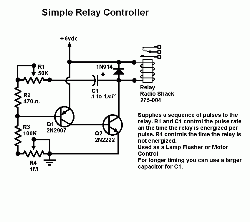 ------------- John DeRosa (Hotwaterwizard)
Stockton California
When in doubt, try it out !
Posted By: hotwaterwizard
Date Posted: April 27, 2006 at 12:08 AM
You could use a regular Automotive Relay if you add a transistor to the output of the 555. 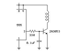
------------- John DeRosa (Hotwaterwizard)
Stockton California
When in doubt, try it out !
Posted By: rajkovic
Date Posted: April 27, 2006 at 3:30 PM
I appreciate your help. I need to run my horns on 12V dc, so I dont think the first one will work. Well then, I' ll use my configuration of two relays and connect the 2. hotwaterwizards configuration on second relay. I thought that NE555 chip is capable of running 500mA on exit. 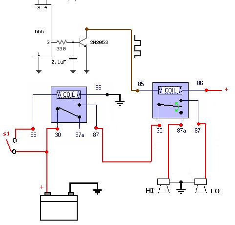
Thank again....
Posted By: hotwaterwizard
Date Posted: April 27, 2006 at 8:46 PM
I found a better transistor interface.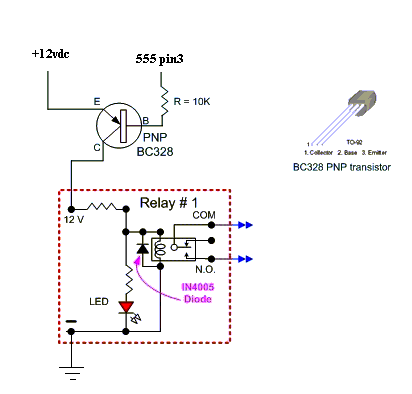 https://www.overclockers.com/tips1122/index03.asp ------------- John DeRosa (Hotwaterwizard)
Stockton California
When in doubt, try it out !
Posted By: rajkovic
Date Posted: April 28, 2006 at 7:14 AM
I need to know, whether signal on 555 pin3 starts with positive value and after calculated time (R1,R2,C1) drops to negative. 
or the other way 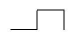
Posted By: hotwaterwizard
Date Posted: April 28, 2006 at 8:59 AM
Here are some links that will help tou with the 555. I think you can force it high or low with the reset mode on the timer. https://www.uoguelph.ca/~antoon/gadgets/555/555.html http://home.cogeco.ca/~rpaisley4/LM555.html https://www.eleinmec.com/article.asp?1 ------------- John DeRosa (Hotwaterwizard)
Stockton California
When in doubt, try it out !
Posted By: hotwaterwizard
Date Posted: April 28, 2006 at 9:31 AM
You could always go low tech 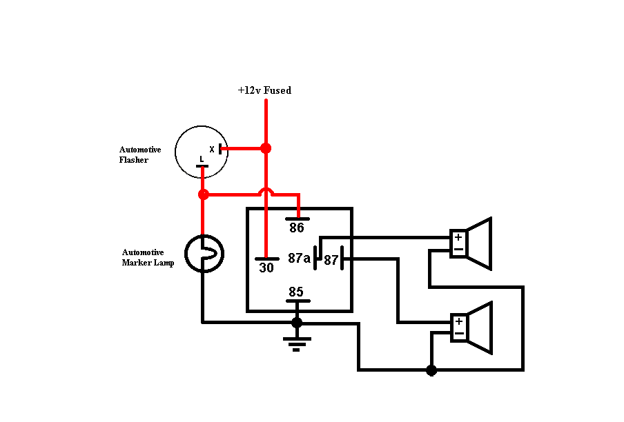
------------- John DeRosa (Hotwaterwizard)
Stockton California
When in doubt, try it out !
|