I am interested in a module that would turn on a negative(-) output upon starting the car, then turn OFF this negative(-) for exactly two seconds(only once) then turn back on the (-)negative output again till the car is shut down
Can someone please help me figure out what I need to do this setup?
I also have a question about the Radio on until door opened (retained accessory power) relay diagram, It says "If you want to prevent 12V+ from feeding back into the accessory circuit or have more than one device on this circuit and do not want all of them to stay powered, you can isolate the device you want to stay powered by cutting the accessory lead going to it and adding two 1 amp diodes and an additional relay as shown below. The first diode near the top left of the diagram is to prevent 12V+ from going back into the accessory circuit. The second diode between terminals 87 and 86 prevents the radio from pulling current through the first diode. If the second diode is not in place, the first diode will become toast. The additional relay is needed to prevent the radio from turning off when the key is in the accessory position and a door is open."
I want the Radio to run under normal operation but then be able to stay on till the drivers door is opened, which of the two options should I select Top Or Bottom?
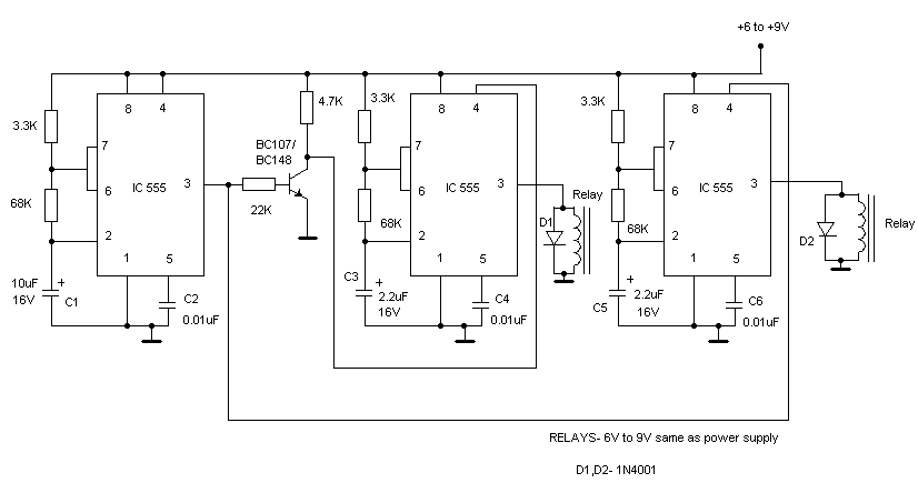
You could make a special circuit with 555 timers but you need to have a basic knowlege of electronics. Example
-------------
John DeRosa (Hotwaterwizard)
Stockton California
When in doubt, try it out !
You could modify this circuit for your needs
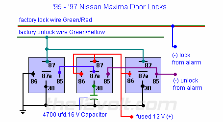
https://www.the12volt.com/request/95maxima.asp#95max
https://www.the12volt.com/images/95maximadl.gif
-------------
John DeRosa (Hotwaterwizard)
Stockton California
When in doubt, try it out !