multiple horns with one switch
Printed From: the12volt.com
Forum Name: Relays
Forum Discription: Relay Diagrams, SPDT Relays, SPST Relays, DPDT Relays, Latching Relays, etc.
URL: https://www.the12volt.com/installbay/forum_posts.asp?tid=81686
Printed Date: April 18, 2026 at 10:01 PM
Topic: multiple horns with one switch
Posted By: bsd1
Subject: multiple horns with one switch
Date Posted: August 16, 2006 at 7:24 AM
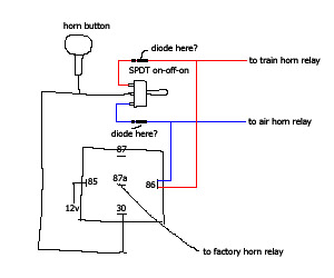
I want to have 3 different types of horns and honk either one of the three in certain situations. But no more than one horn will be honked at the same time. All 3 of them use negative pulse to energize their respective relay.
I will use the factory horn most of the time and center-off the SPDT switch so when the factory horn honks the air/train horns are disabled, if my logic is correct, even though the middle pin of the SPDT switch has ground ready when the horn button is pushed, but if it sits at center-off position, so both train/air horns do nothing.
However, if either the train horn or air horn honks, if I am correct, it should energize the normally-closed relay on my diagram and connect pin 30 to pin 87, as if the factory horn wire was cut off.
Let me know if this still makes sense.
My major question would be, do I need the diode on blue and red wire? If so, are they in the right position and direction to protect my switch? Do I need a fuse the 12v+ at pin85 on the relay, 5A? Basically everywhere except pin85 on the diagram is using ground signal.
Do you see any problem with this multi-horn setup? Or any better solution?
Replies:
Posted By: ff-mike
Date Posted: August 18, 2006 at 11:51 AM
The logic looks good to me, and should work as you intend.
The diodes will be needed
I had done something similiar a few years ago. The only oops I had was that one of the units triggered on 12v+ or ground, and was getting feedback from the horn relay.
Posted By: bsd1
Date Posted: August 20, 2006 at 4:10 AM
ff-mike wrote:
The diodes will be needed
When it comes to diodes I am pretty much clueless. I still don't quite understand the confusing diode tutorial here. Anytime the cathode is more positive than the anode, no current will flow But I am dealing with plain negative current, very confusing. Anyhow please tell me base on my diagram do I have the A and K the correct direction?
ff-mike wrote:
and was getting feedback from the horn relay.
Even pure ground current also?
hotwaterwizard wrote:
Where is the third horn?
You only have 2 horns hooked up.
I think You will need 2 relays for this job
1) factory horn -> at 87a normally closed relay
2) train horn -> one of the ON position of SPDT switch
3) air horn -> the other ON position of SPDT switch
If I need 2 relays for my current setup, then something MUST not be correct. I'd like to find out what mistake I have made on my logic.
I definitely aware if my horn button doesn't send very strong constant ground, I will add a relay in between.
Like many have said, a continue engerizing relay will drain battery. I may use ignition 12V instead, in case I forget to turn my SPDT switch back to its CENTER OFF position.
When this is taken care of, I will move on and add this 3 horns into my existing alarm setup, but that'd be another topic.
Posted By: hotwaterwizard
Date Posted: August 20, 2006 at 11:56 AM
I did make a diagram with 2 relays but in reviewing your diagram again I found that yours would do the same job. The diodes are not needed (on my diagram) if I look at this right. And I see no drain if the horn button is not pushed. A Diode is just like a check valve. It lets voltage Flow in only one direction. You can use it in many applications. The line on the Diode just shows you which leg stops flow. The arow shows the direction of the flow -I<- 
------------- John DeRosa (Hotwaterwizard)
Stockton California
When in doubt, try it out !
Posted By: joemcm
Date Posted: September 26, 2006 at 8:14 PM
Im looking to do something similar, but with just the factory horn and an air horn. How would the wiring be different?
thanks
Posted By: bsd1
Date Posted: September 27, 2006 at 5:16 AM
That'd be much easier. I am lazy to draw the diagram, maybe you can for confirmation.
85 -> (+) Ignition fused 12V
86 -> (-) SPST switch (ON-OFF)
30 -> (-) Horn button
87a -> (-) Factory horn relay
87 -> (-) Air horn relay
Use non-illuminated toggle/rocker switch. Connect the load terminal to pin86 of the relay. Connect the other terminal to chassis ground. The switch itself should have 2 terminals.
You don't have to use ignition 12V but recommended. If it was for foglight, it would be shut off with parking light. But for your situation if you forget to turn off the toggle switch the continue-energized-relay could drain your battery. Using ignition 12V approach you just can't use air horn while engine off but the factory horn will continue to function as normal.
Air horn relay to 87, straight forward.
Horn button to 30 and factory horn relay to 87a, they really are one wire. You need to trace down your factory horn wire and cut it. The one end closes to the horn button, that goes 30 of the relay. The other end, that's the one to your factory horn relay, goes to 87a of the relay. You may want to check out the starter kill basics here, the terminology are identical.
Posted By: hotwaterwizard
Date Posted: September 27, 2006 at 8:23 AM
 ------------- John DeRosa (Hotwaterwizard)
Stockton California
When in doubt, try it out !
Posted By: joemcm
Date Posted: September 27, 2006 at 10:19 AM
thanks I will try that out
|