Hello,
I used to have a bunch of neon lights, cold cathodes, etc. in my car, and, well, I actually have a car I don't want to put a bunch of holes in, so, I've decided to put all those lights in the party room in my house, at least put 'em to use.
I am using a computer 350 watt power supply for the 12 volts. What I want to do is wire a set of my lights up so half of then blink on and then the other half blinks on (as the first half blinks off) etc. Sort of like blue, green, blue, green, etc.
I know how to use an 8616 relay to turn a +12v current into a 0v current- I currently use it in my sound-activated setup where one set turns on with the bass, and the other set turns off.
So really, all I need is to find a way to alternate 12v current and no current every second or so. Conveniently, cars already do this, so I stopped at autozone and bought the cheapest blinker relay I could find. I got the "Tridon Stant" 550 blinker (thermal, I don't know what that means). The pins are arranged like | _ | and labelled L, P, and X respectively. Although there weren't any number specifications, I figured they were 85, 87, and 86 respectively.So, I hooked up the 85 and 86 up to the power supply and then the 87 up to the positive end of a 12v indicator, and hooked the - end of the LED to the power supply's - wire. When I turn on the power supply, I hear the relay click, but then the power supply turns off and won't turn on for a few seconds (the way it usually does when I short two wires). Swapping around the 86 and the 85 has the same effect, any other combination of pins has no effect.
What am I doing wrong?
Oh, I suppose I should have mentioned.
I've looked at the simple 555 timer circuit that everybody in EE gives you. I guess I could do that, but I am horrible with soldering IC stuff and I do not have the necessary equipment. I'd prefer a more idiot-friendly solution, if possible, thanks.
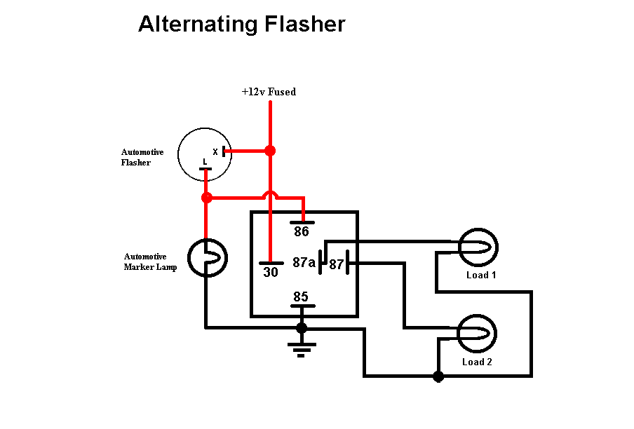
try doing this: get a regular two post flasher relay and a regular SPDT car relay (five post) hook the ground from the power supply to 85, 12 volt pos. to 30, pos. of one set of lights to 87, the other to 87a and hook up 12 volts pos to one post of the flasher (doesnt matter which) and the other post to 86 of the SPDT relay. this should do the trick
Have you ever seen a car with a blinker on that is going really fast. Thats because one of the buls in the circuit has gone out causing a change in resistance. I don't know the specifics of how that would affect your application but bear in mind that alot of those flashers are dependnt upon a specific resistance for funtionality.
Your computer power supply may not actually be able to supply the amount of Amps on the +12V rail that the label indicates without a significant load on the +5V rail. They're designed to power a computer which normally has a hefty +5V load and the power supply designers figure that into how the voltage regulation works. I've tried to use a number of computer power supplies to power 12V lights and run various problems on most of them - from sagging +12V voltage to the power supply just shutting down with the sudden initial load.
I have a police light bar in my office that is powered by an old PC power supply and I had to use delay circuits to turn parts of it on a fraction of a second later so that the initial turn-on current wouldn't overload the power supply and make it think it's been short-circuited.
Also, you may need to draw about 3A across that flasher unit to make it think it's in a normal car turn signal circuit and have it flash at the normal rate. That means if you are using a relay wired up to the flasher, you'll need to put about a 4 Ohm 50W resistor in parallel with the relay coil. Instead of a big resistor you could use two 1156 bulbs as a dummy load for the flasher and wire a relay (terminals 85 and 86) in parallel with the bulbs.
You can avoid having to do that if you buy an aftermarket flasher that is intended for LED turn signals. They flash at the same rate regardless of how small the load is. Some of those flashers are good up to a 20A lighting load so you might not even need a relay.
-------------
John DeRosa (Hotwaterwizard)
Stockton California
When in doubt, try it out !