Tricky momentary to momentary
Printed From: the12volt.com
Forum Name: Relays
Forum Discription: Relay Diagrams, SPDT Relays, SPST Relays, DPDT Relays, Latching Relays, etc.
URL: https://www.the12volt.com/installbay/forum_posts.asp?tid=84248
Printed Date: May 15, 2026 at 12:22 AM
Topic: Tricky momentary to momentary
Posted By: 12vlost
Subject: Tricky momentary to momentary
Date Posted: October 17, 2006 at 2:49 PM
Hi Guys! need a diagram for a relay to make a mom pulse to a mom pulse. The receiver i have wired is for a garage door,two wires from the bell push to the receiver and the internal relays click and it opens fine using the transmitter, only problem is it stops the bell push from working! So, the way i see it is, the mom pulse is n/c in the receiver so its stopping the bell push from working unless someone kind has another suggestion?
Replies:
Posted By: master5
Date Posted: October 18, 2006 at 5:50 AM
I want to help you and probably can. I need more info however. If this is a 12v dc system i can perhaps figure out a circuit for you using timer or latching relay circuit. Please post info with more specifics, I am having trouble understanding what you are actually trying to do. and what is a "bell push"? I am a dumb american and never heard that term. Thanks -------------
Posted By: 12vlost
Date Posted: October 18, 2006 at 3:10 PM
Cheers buddy...dumb American?..no way.... Anyway I'll try and be more specific. I have a garage door operated by a "bell push switch" which is basically a mom non latching switch n/o...I have taken a pair of wires from either side of the switch to an Autolock 12 volt 18 channel receiver to control the door remotely from the transmitter..I then wired the receiver with both wires on channel one so when the transmitter is pressed it opens the door..this works fine...however the mom switch will not operate anymore. To confuse matters I also have two more receivers wired in to the same wiring operated by two seperate transmitters tied into a homelink system, I have a feeling these are a normally open system which may be confusing the circuit as i think the autolock system may be n/c as these other receivers also cease to operate.. The whole system works fine until i connect the Autolock receiver.. Any clearer?..stick with it..please :-)
Posted By: the12volt
Date Posted: October 18, 2006 at 3:21 PM
The garage door opener obviously needs to see the two contacts momentarily closed to operate in either direction, correct? If this is the case, each switch should be connected in parallel with the two contacts and not through the additional device you just added for them all to work. A diagram of how you have all of these wired to the garage door opener contacts would help us solve your dilemma. -------------  the12volt Support the12volt.com the12volt Support the12volt.com
Posted By: 12vlost
Date Posted: October 18, 2006 at 3:58 PM
Yeah, thats right, the garage door needs to be momentarily closed to open/close. The other receiver works fine as it has the option of n/c & n/o on its wrining options.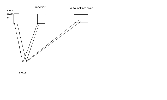
Posted By: the12volt
Date Posted: October 18, 2006 at 4:02 PM
If the Autolock receiver will work as normally open (like all your other switches/receivers), wired in parallel with all the other switches/receivers to the two contacts on the garage door opener and you should be good to go. ------------- the12volt Support the12volt.com
Posted By: 12vlost
Date Posted: October 18, 2006 at 4:13 PM
Is it wired in parallel at the moment?..sorry if thats a dumb question... i think this is the issue, maybe the Autolock receiver is n/c which is why i may need a relay to make it n/o? This may explain why the rest of the receivers/switch wont function when the Autolock systm is wired in..
Posted By: the12volt
Date Posted: October 18, 2006 at 4:40 PM
Ahh, I see. I thought you meant the Autolock unit had the option of being normally open or normally closed. Since it's normally closed, wire it with an SPDT relay to its outputs as follows: Connect one of the two leads of the Autolock unit to ground.
85 to the other lead of the Autlock unit
86 to 12V+
30 to one garage door contact
87a to the other garage door contact ------------- the12volt Support the12volt.com
Posted By: the12volt
Date Posted: October 18, 2006 at 4:46 PM
BTW, connect all the other switches/receivers (normally open) in parallel with terminals 30 and 87a of the relay described above to the garage door opener contacts. When you activate the Autolock unit, the coil of the relay will de-energize and the normally closed contacts of the relay (87a and 30) will have continuity. ------------- the12volt Support the12volt.com
Posted By: 12vlost
Date Posted: October 18, 2006 at 4:54 PM
Hey, thats fantastic!! Will give it a go tomorrow as its kinda late here now..will report back buddy.
Posted By: the12volt
Date Posted: October 18, 2006 at 4:55 PM
About 11:00 PM there, eh? ;) ------------- the12volt Support the12volt.com
Posted By: master5
Date Posted: October 18, 2006 at 11:50 PM
Glad you got help before I got back. Sounds like it's on the money. Let us know how it works out. -------------
Posted By: 12vlost
Date Posted: October 19, 2006 at 1:54 AM
Hey Guy's..worked an absolute treat..fantastic. Will donate to this great site and no doubt will be back witn some crazy new schemes... Thanks!!
Posted By: 12vlost
Date Posted: October 19, 2006 at 2:25 AM
Guy's, have disovered a minor/major flaw which should be easily rectified? When the 12v is cut to the relay the door lifts...this will cause security issues as the power to my home does get cut off from time to time. Would a diode inserted the correct way solve this? Thanks.........warned you I'd be back..he he
Posted By: master5
Date Posted: October 19, 2006 at 2:49 AM
Well I am surprised the door will lift if there's no power. Do you have some kind of a back up power system for the garage door? I can't imagine how a simple diode can help in this case if a break in 12v to the relay is causing the door to open. If I am understanding your problem correctly (once again I think some more specifics are required) you need some kind of a 12v backup system to keep 12v on the relay at all times. Any standard 12v security back up battery system should do the trick (they are relativly inexpensive so shop around) but once again, how does the door open if powers out?? -------------
Posted By: master5
Date Posted: October 19, 2006 at 2:54 AM
I am about to retire for the evening so I will check back again in the am. take care............ -------------
Posted By: 12vlost
Date Posted: October 19, 2006 at 2:59 AM
I think you are on the money with the UPS back up... The power goes off frequently so a decent size back up system will allow me to open the garage door at the same time as keeping 12v to the relay.
Posted By: 12vlost
Date Posted: October 19, 2006 at 3:04 AM
Also I wasn't too clear buddy (again) :-) I basically have the 12v transformer plugged into a 240v socket which powers the realy and autolock system, when i switched this off power was still present at the garage door motor from another socket, so it lifted. I guess if there was a total power loss the door couldn't lift..oops..my bad!! Still the UPS would be a bonus.. Thanks Bud..
Posted By: master5
Date Posted: October 19, 2006 at 1:06 PM
Alrighty then, that mystery is solved. Appears the root of the power problem comes down to the utilities company in your area. Where I live a hurricane knocked out the power to my home for over 2 weeks. Just had to get used to cold showers in the dark. A back up generator would have come in quite handy. Oh well, such is life. Take care. -------------
|